
Search

SealBoss News / Blog

Crack Injection Guideline – 1 2 3 at 45 Degree

Crack Injection Guideline
1 - 2 - 3 at 45 Degree
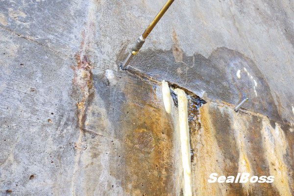
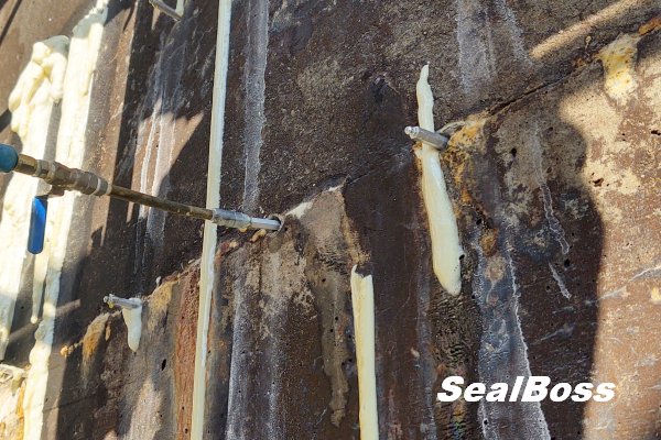
SealBoss 1 2 3 at 45 Degree Injection Guideline Leak-Seal & Water Stop Crack Injection

Crack Injection Guideline
1 - 2 - 3 at 45 Degree

Injecting Trust - One Crack at a Time

A Comprehensive Injection Guideline featuring Detailed Information on Injection Packers and their Correct and Intended Use

Introduction

Cracks in concrete structures are more than just cosmetic issues—they can compromise integrity, allow water intrusion, and accelerate rebar corrosion. The SealBoss 1-2-3 at 45 Degree Crack Injection Guideline provides a proven, systematic approach to crack injection that ensures effective leak sealing and structural protection. By following three critical steps—preparing and mapping packer placement, installing the packers, and executing the injection at a 45-degree angle—contractors can achieve durable, high-quality results. This article outlines best practices, technical details, and important considerations to help professionals optimize their injection process and maximize success, one crack at a time.

The SealBoss 1-2-3 at 45 Degree Crack Injection Guideline

  • Step 1 – Preparing and Mapping Out Packer Placement
  • Step 2 – Installing the Packers
  • Step 3 – Executing the Injection Process
  • 45-Degree Angle – Recommended Packer Angle / Positioning Guideline

Optimal Techniques and Considerations

The SealBoss 1-2-3 at 45 Degree Injection Guideline highlights the three fundamental steps of the injection process while emphasizing the importance of a standard 45-degree angle for packer placement. Although the 45-degree angle is a widely accepted practice, certain situations may require deviation from this rule, as discussed in this article.

Additionally, it is advised to target each injection port three times during the injection procedure – as a general rule – to ensure adequate density and penetration of the chemical grout within the structure. Injection Packers that persistently absorb product should be injected repeatedly, as many times as needed, to ensure a lasting seal.

Injection Packer Spacing

Mechanical injection packer spacing, also referred to as port spacing, in the context of leak-seal crack injection is contingent upon several site-specific conditions, such as crack width, substrate thickness, water flow, and product properties.

In numerous instances, an 8-inch (20 cm) to 1-foot (30 cm) on-center spacing serves as a suitable initial distance. Hairline cracks necessitate tighter spacing, as the product is less capable of traveling far. Consequently, the tighter the cracks, the closer the required spacing.

Injection Packer Placement

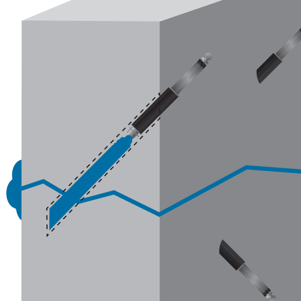
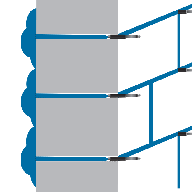
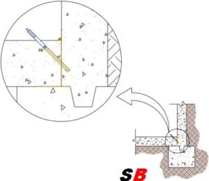
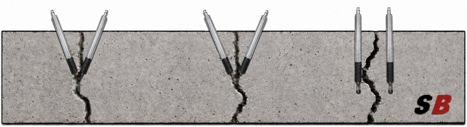
In the majority of cases, injection packers should be arranged in a staggered manner by alternating drill holes to the left and right of the crack while drilling at a 45-degree angle toward the crack, thereby forming a stitch grouting pattern. This method enhances the likelihood of intersecting the crack during drilling and reduces the probability of concrete cracking and spalling during packer installation or the high-pressure injection process. Injection should commence from the bottom and proceed upward.

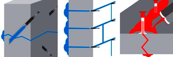
The illustration below shows how angled drilling increases the likelihood of intersecting the crack, as shown on the left and in the center. In contrast, straight drilling often misses the crack, creating a dead-end hole, as shown on the right. Packers installed in these holes do not communicate with the crack, preventing the injection resin from filling and sealing it.
Angle Drilling Injection Packers SealBoss

45 Degree Angle Drilling and Packer Placement

The optimal method for packer placement involves positioning at a 45-degree angle. For structures with a thickness exceeding 6 inches (12-15 cm), SealBoss recommends a 45-degree angle as the most effective strategy for intersecting the crack at the midpoint of the structure. This is accomplished by initiating drilling a few inches to the left or right of the crack at an angled trajectory toward the crack itself, rather than drilling directly into it. This technique enables the requisite “inside-out” product flow for optimal crack penetration.

For instance, in a 10-inch thick concrete wall, one should move approximately 4-5 inches (8-10 cm) away from the crack and drill at a 45-degree angle toward it to attain the desired target. Initiating drilling with a straight entry and subsequently angling the drill at the required angle is beneficial.

Typical drill spacing along the crack’s surface ranges between 6-12 inches (10-20 cm) depending on the crack’s thickness. Hairline cracks necessitate closer spacing than larger cracks, as the material will not travel as far. Stagger drill holes from one side of the crack to the other, intersecting the crack during drilling.

Optimizing Drill Hole Distance from the Crack 

When determining the spacing of drill holes from a crack for chemical grout injection, it is essential to understand the relationship between the hole’s distance from the crack and the depth at which it intersects the crack. Here is a detailed explanation:

  • Depth of Intersection: The greater the distance between the drill hole and the crack, the deeper is its intersection with the crack inside the structure, leading to a deeper point of injection.
  • Considerations for Thicker Structures:  In thicker structures, a deeper injection point is usually favored. Yet, it is essential to factor in the drill bit’s length and reach, as they play a crucial role in determining the optimal distance for the drill hole. Always allow for a margin of error and ad at least a margin of 2 inches to the calculated drill bit reach needed.
  • Avoiding Dead-End Drill Holes: A drill hole that misses the crack cannot facilitate the injection of the chemical grout into the structure. Such holes are termed “dead-end drill holes” and are ineffective for the purpose of grout injection.

Determining the Required Minimum Length for a Drill Bit

When drilling at a 45-degree angle, we encounter a specific triangle called the 45-45-90 triangle, which follows the principles of the Pythagorean theorem.

In this 45-45-90 triangle, both legs, marked “X”  are of equal length. X is the distance the drill hole is placed away from the crack. Therefore, when drilling at a 45-degree angle, if we assume the crack is perpendicular to the surface, the depth at which the drill hole intersects the crack will be the same as the distance of the drill hole from the crack. To determine the minimum drill depth, or the distance from the drill hole surface to the crack, use the formula:
Distance from crack X √2, which is approximately 1.414.

To simplify and account for variations we use the factor 1.5 to calculate the absolute minimum drill hole depth necessary to intersect the crack. 

For a 5-inch distance from the crack, the calculation would be: 5 × 1.5 = 7.5 inches. Therefore, the drill hole should be at least 7.5 inches deep to guarantee intersection with the crack for injection in near perfect conditions.

For a 6-inch distance from the crack, the calculation would be: 6 × 1.5 = 9 inches. Therefore, the drill hole should be at least 7.5 inches deep to guarantee intersection with the crack for injection in near perfect conditions.

Now add at least 2 inches of drill bit reach to the calculation. It is essential to remember that not all cracks might run perfectly perpendicular to the surface, so always consider the specific conditions of your project.  

In summary, while determining the placing of drill holes, it is important to balance the desired depth of injection with the capabilities and reach of your drilling equipment to ensure effective grout injection.Remember, the effective reach of a drill bit and its actual length differ.

Always ensure your drill bit has the necessary length to effectively intersect the crack!

General Injection Packer Preparation – Drill and Flush


Safety Gear

Consistently wear appropriate protective gear and goggles, adhering to data sheet and SDS instructions.

Cleaning

If required, clean the crack or joint’s face using a wire brush, pressure washing, or similar method. A clean surface facilitates the identification of cracks and problematic areas.

Spacing

Mechanical injection packer spacing, also known as port spacing, is contingent upon various site conditions such as crack depth and width, substrate thickness and state, water flow rate, and the product’s physical and chemical properties.

An 8-inch (20 cm) to 1-foot (30 cm) on-center spacing is suggested for the majority of situations. Hairline cracks necessitate tighter spacing compared to wider cracks. The tighter the cracks, the closer the required spacing, as the product must travel deeply enough into the structure to form a permanent seal.

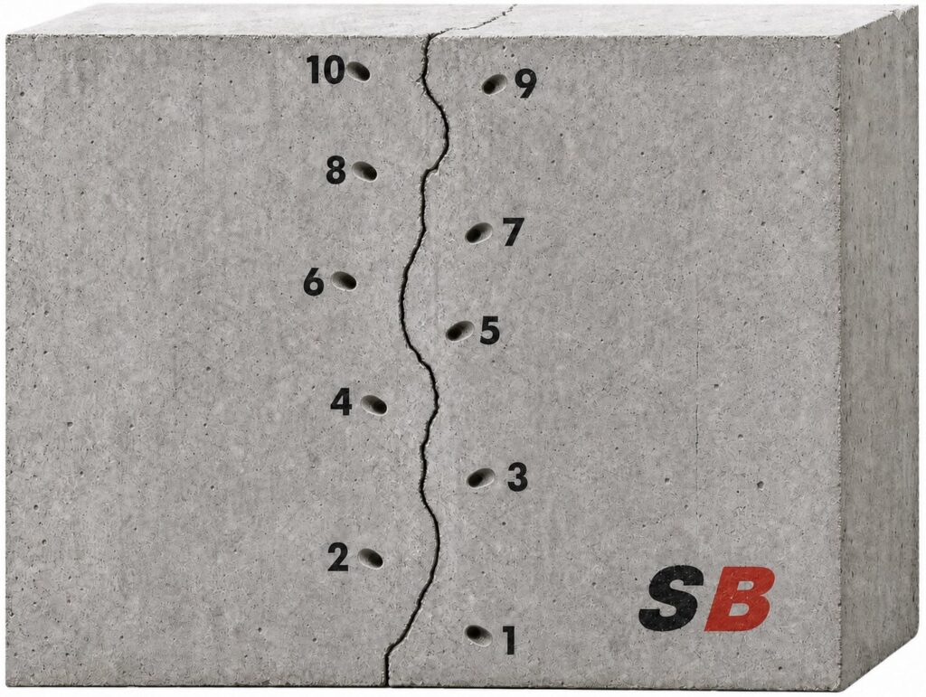
Determine the spacing, pattern, and depths of the drill holes. Based on the crack’s width, space the packers at a distance of approximately 6-18 inches (10-45 cm). The tighter the cracks, the closer the required spacing. Hairline cracks result in limited water stop and leak-seal grout travel, necessitating tighter packer spacing, while wider cracks permit easier flow and broader packer spacing.

Stagger drill holes from one side of the crack to the other (left/right), thus forming a stitch grouting pattern. This technique increases the chances of intersecting the crack during drilling while decreasing the likelihood of cracking and spalling the concrete during packer installation and the high-pressure injection process.

Typically, injection should begin at the bottom and move upward, pushing the product against gravity and water flow, thereby achieving a higher density in the process.
Injection-Packer-Drilling-Pattern-45-Degree-Holes SealBoss


Exceptions to the 45 Degree Injection Rule – Straight Drilling

As with any rule, the catchy SealBoss 1-2-3 at 45-Degree Rule has its limitations and exceptions. Here are three notable examples:

  • Drilling into Joints
    Drilling into joints, such as concrete tunnel segments, is predominantly performed in a straight manner.
  • Thinner Stuctures
    Concrete structures with a thickness of less than 6 inches may not permit angle drilling, as this can result in cracking and spalling of the concrete.
  • Badly Deteriorated Substrate
    Similar issues can occur in severely deteriorated concrete substrates and in concrete of inferior quality. In such situations, it is recommended to drill and install packers directly into the crack without completely penetrating the structure.

SealBoss offers an extensive range of injection equipment and pumps to accommodate your project. Consult a SealBoss technician for detailed information and assistance. We look forward to helping you with your project.

Drill Dust

When drilling deeper holes, periodically extract your drill bit to remove drilling dust and prevent your drill from binding up.

Rebar

Most concrete structures contain rebar steel reinforcement to provide structural strength. In an ideal, crack-free structure, concrete protects the rebar from corrosion by insulating it from moisture and air while maintaining a high pH environment. However, when cracks form, this shield is compromised, allowing air, environmental gases, and water to cause carbonation, and subsequently corrosion of the rebar, which  forms rust expands to expands its original volume. The expansion of rusted rebar exerts high forces against the concrete, resulting in further deterioration, cracking, and spalling. Chemical grout injection protects rebar and can mitigate these processes.

Rebar often slows down the drilling process. When your drill bit contacts rebar, the sound changes, the quantity of drilling dust may be reduced, and the progression slows down or may even stop.

Some drill bits enable drilling through rebar, although this is generally not recommended and may even be prohibited, as it can weaken the concrete structure. In such cases, relocating the drill hole is the only option. If you repeatedly hit rebar, consider drilling straight into the crack. Dead-end drill holes, the holes that are not used for injection, must be patched and sealed before injection to prevent leakage.

Flushing / Cleaning Drill Holes Prior to Injection

Overview

Drilling debris can thicken the product during injection, resulting in higher injection pressures and reduced penetration in fine cracks. It is best practice to remove concrete dust and debris from the drill holes by flushing with a water hose until clean water is observed. You can use a water hose to flush debris from the hole.

Vacuuming out the dust can also be helpful if flushing is not possible.

Blowing out the debris is another option; however, be aware that dust can be an inhalation hazard, and appropriate gear is mandatory.

Flushing / Cleaning of holes is not necessary if water is actively running from your drill holes.

Drill Hole Water Flushing Detail

Low Pressure Flush

For low-pressure flushing, simple tools like a plastic water squeeze or spray bottle suffice. This method can remove debris from the drill hole and introduce water into the drill hole.

If available on site, a water hose can be used to flush the drill holes.

Using a Dedicated Flushing Water Pump

A dedicated water injection pump is suitable for both low-pressure drill hole flushing with a hose and on-site pressure crack flushing with water through injection packers.

While drill hole flushing serves to remove debris from the hole only, high-pressure water flushing can provide insights into material flow, expected product penetration distance, and introduce moisture to enhance product reactivity.

For such high-pressure applications, a dedicated water flushing pump is essential.

After clearing the drill hole, an injection packer is positioned. The water pump is then linked to channel water under high pressure via the injection packer into the into the crack, flushing it in the process.

If the crack remains unresponsive to taking on water, it might indicate that the hole is not linked to the crack. In such cases, a new drill hole has to be established and retested with water.

While high-pressure flushing is not typically required for most injection projects, it can offer benefits in specific scenarios.

It is imperative not to use the same pump for water injection that you use for dispensing polyurethane resin. Given that polyurethanes are activated by water, even the slightest moisture can result in pump malfunction.

Final Thoughts

Equipment limitations may render flushing infeasible; however, most injections will succeed without additional water introduction, even in seemingly dry crack environments. If the product does not immediately contact water, it will cure over time as natural moisture in the concrete stimulates curing and hardening, potentially at a slower pace.

Additional Injection Packer Installation Recommendations

Mechanical Packer Fundamentals

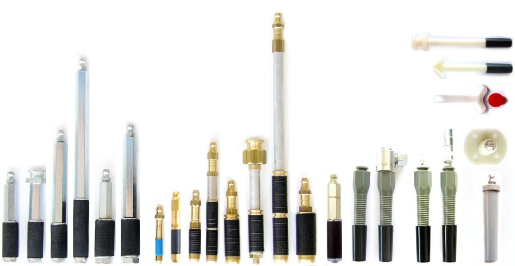
For optimal performance, packers and drill holes must possess adequate quality to endure injection pressures without leakage or displacement within the crack. Notably, even superior packers may rupture or leak under certain conditions. SealBoss Mechanical Packers, available in various sizes and designs, are recommended for pressure injection. These packers feature a threaded shaft with a rubber base; upon insertion, tightening the shaft compresses the rubber within the drill hole, generating a compression seal. Standard packer diameters range from 1/4 to 3/4 inches, with industry norms between 3/8 and 5/8 inches. In poured concrete substrates, drill holes serve as solid channels directing resin to the crack, enabling the use of shorter packers. In substrates with potential voids, such as block walls, stone, and brick, SealBoss advises employing longer packers to ensure a definite grout delivery channel to the crack being sealed.

Mechanical Packers Installation

To seal against the drill hole, mechanical packers require tightening, which expands the rubber seal. Packers may be pre-tightened by hand to seat the rubber snugly, approximately 1/4 inch (5 mm) inside the drill hole. Correct installation prevents concrete cracking around the drill hole’s exterior. Depending on packer design, using an appropriate ratchet/nut, wrench, or electric driver for tightening is highly recommended. Packers should be securely tightened to withstand injection pressures without over-tightening.

SealBoss Hammer-In Ports

SealBoss Hammer-In Ports are also frequently utilized. These ports are seated using a hammer at moderate force, with an electric driver or hand tool and a suitable socket employed to screw the zerk fitting into the port. Hammer-in ports typically do not achieve the same injection pressures as mechanical packers and should be reserved for applications where maximum injection pressures are not essential.

Packer Connectors

Packers are typically equipped with a quick-connect system, either a zerk type or button head/slide coupler type.

Zerk Type Connector

The zerk type is most prevalent. Applicators must push the coupler over the zerk fitting and maintain alignment with the packer. To disconnect, applicators “break” the connection by pushing the connector sideways.

Button Head / Slide Coupler

The button head type provides a more secure connection. The operator slides the coupler on and off the packer, ensuring a secure, tight connection that is less prone to unintended disconnection and leakage. When executed properly, the applicator does not need to hold the coupler in place, a significant advantage in overhead injection and instances requiring large product volumes through one packer.
SealBoss Packers

SealBoss offers an industry-leading array of injection packers and ports for diverse situations and requirements. Contact a SealBoss representative for packer recommendations tailored to your project.

Injection Products


Before You Start Injection

Before injection, review the product datasheet instructions. Ensure your pump is in fully operational condition and completely devoid of moisture before preparing SealBoss Water Stop and Leak Sealing Products for injection.

It is prudent to flush the pump with SealBoss R70 before using any resin/foam grout.

Injection Procedure

When products are prepared for injection, have a cup available to dispose of some resin to ensure purity. Start the pump at the lowest pressure setting. After connecting your grout injection hose to the secured and tightened packers, initiate the injection process.

Use the shut-off valve at the injection hose’s end whenever the hose is moved, remember that some pumps need to be manually stopped .

Starting from the bottom, securely connect your injection line to the packer and commence with the lowest pressure capable of moving resin into the crack. Generally, injection pressure will decrease as material flows, but pressure may need to be increased as products thicken and move into tighter cracks and fissures.

Maintain a slow injection rate as resin begins to show and flow from the crack. Pausing and restarting the process for a minute may be necessary to allow material reaction and thickening.

Monitor consumption rates and cease injection when consumption equals leakage. A typical observation involves reduced water flow from the crack’s face and/or reacting material exiting the crack’s face. This indicates successful penetration and results.

If the product does not advance along the crack, disconnect and proceed to the next port. Applicators must ensure sufficient material is injected into each crack to achieve optimal product density for a durable seal.

It is recommended to inject three to five packers while observing product flow, travel, and refusal from the crack.

Reinjecting those three to five packers—typically up to three times (1-2-3 at 45 degrees) or until product refusal—is crucial. The crack must be adequately filled with as much product as possible without excessive product loss from the crack. Sufficient material consumption and product density in the injected area must be monitored to achieve a solid and successful repair.

Injection Packers that continue to consume considerable product amounts should be injected a third time or as often as necessary to create a permanent seal.
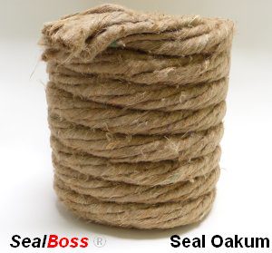
SealBoss Oakum Soakum Technique

In cases where excessive resin flows out or washes out due to high water flow, resin-soaked SealBoss Oakum can be employed to form a temporary plug, allowing the product time to react, expand, and seal.

Caution: Be prepared for the possibility of product ejection from the structure or around drill holes, as well as packer blowouts. High-pressure injection equipment may cause product to travel further than anticipated, potentially appearing several feet from the injection point. Small cracks may become visible after the injection process.

Quality Injection Job

Injection often necessitates a two-person team, with one individual operating the valve and hose while another manages the pump. Create a dense seal! Inadequate material consumption alone can yield differing results in the same injection application. If the crack is not accepting any product, it may be due to insufficient drilling depth or crack direction on the opposite side. In such cases, drill from the opposite side of the crack and ensure intersection with the crack.

Packer Removal

Once the material has fully cured, packers can be removed by loosening the shaft. Some applicators opt to leave the rubber base in the wall and patch the drill hole, while others remove the entire packer before patching. In certain injection applications, packers may remain in place permanently. This decision is at the discretion of the applicator or owner. A final cleaning of the crack’s face is necessary to remove cured product using a wire brush, pressure washing, or other appropriate methods. The substrate is then prepared for the final finish.

SealBoss R70 Pump Flush for Clean-up

DO NOT CLEAN WITH WATER. If allowed on the job, initially flush all dispensing equipment with a small amount of solvent, such as xylene, to cut the product. Follow this step by generously flushing with SealBoss R70 Pump Flush & Cleaner to protect hoses and lubricate the pump. Avoid using solvents for the final flush, as this can reduce the lifespan of your equipment.

Exception – Equipment for SealBoss 2400 Acrylate is cleaned with water. Consult the data sheet for details.

Inquiries, Comments, or Requests?

Contact us now at 714-662-4445 and request your technical consultant!

Contact Your SealBoss ® Technician

Injection Grouting Quality Control: Documentation, Verification, and Follow-Up

SPECIFIED & VERIFIED — PART 4 OF 4

Injection Grouting Quality Control: Documentation, Verification, and Follow-Up

A clear field record helps contractors, owners, engineers, and inspectors understand what was observed, installed, changed, and left for further review.

SealBoss Corp.  •  Technical blog series  •  Technical review required before publication

Part 1
Part 2
Part 3
Part 4

Scope boundary

This part covers the project record, verification, and follow-up. Assessment is addressed in Part 1. This article does not create acceptance criteria, warranty obligations, or project-specific inspection requirements.

Injection work is largely concealed; the record should not be

Injection grouting takes place largely out of sight.

The crew can observe the concrete surface, pump, packer or port, material consumption, pressure and flow behavior, visible returns, and changes in active water. No crew member can directly see every internal crack branch, joint interface, void, cavity, or water pathway behind the structure.

That limitation makes documentation especially important.

A field record does not prove that every concealed opening has been filled. It establishes what was known before the work, which system was used, how the installation progressed, what responses were observed, where the plan changed, and what remained for follow-up.

The record should be useful to the people who performed the work and to those who were not standing beside the pump.

Establish the pre-work condition

Quality control begins before the first drill hole or surface port is installed.

The pre-work record should identify the structure, exact treatment area, relevant drawing or elevation, date, personnel, and environmental or operating conditions that may affect the observation. Photographs and marked plans should show cracks, joints, penetrations, staining, efflorescence, previous repairs, active leaks, and the boundaries of the proposed work.

“Leaking” is often too broad. The report may distinguish steady flow, intermittent discharge, dampness, seepage following rainfall, water under a known operating condition, or a reported leak that could not be reproduced during the inspection.

Where practical, photographs should be taken from repeatable viewpoints. Packer or port numbers, scales, stationing, grid references, or marked elevations can connect each image to the field record.

State the repair objective and governing documents

The report should identify what the injection is intended to accomplish. The objective may involve chemical-grout waterproofing of a defined crack, treatment of a construction joint, localized sealing of a penetration, or a designated curtain-injection area. It should not imply structural restoration unless that function is supported by engineering and product documentation.

The report should identify the documents used to plan and perform the work, including the current product data sheet, SDS, application guideline, pump manual, packer information, project specification, drawings, submittal, method statement, mockup record, inspection plan, and authorized field direction.

Revision dates matter. A document title without a revision or issue date may not establish which instruction the crew followed.

ASTM D8109-25, Standard Guide for Waterproofing Repair of Concrete by Chemical Grout Crack Injection, is intended to assist owners, representatives, architects, engineers, contractors, and authorized inspectors during selection, specification, installation, and inspection. Its multi-party scope supports a record that makes roles, decisions, and observations clear.

Section 4.7 also directs readers to related ASTM practices for chemical-grouting procedures in sewer and manhole work: ASTM F2304, ASTM F2414, and ASTM F2454. Those practices address different applications and should not be treated as SealBoss product instructions.

Identify the exact material and equipment configuration

The material record should be more specific than “polyurethane grout,” “acrylate,” or “epoxy.”

It should identify the exact SealBoss product and variation. Batch or lot information should be recorded when required by the project or current technical documents. Where the system includes an accelerator, catalyst, separate component, static mixer, or another controlled configuration, the record should identify it in the manner required by the controlling source.

The equipment record should identify the pump model, relevant configuration, hose and valve arrangement, coupler type, and packer or port system. The applicable pump manual and application guideline should be referenced.

Substitutions should be recorded when they occur. A different pump, product variation, packer, coupler, hose, cleaner, component, or applicator may affect the original system review. Compatibility should be confirmed rather than assumed.

Use a point-numbering convention that follows the structure

Numbered injection points connect the treatment area to the daily report.

A practical convention can combine the area, structural element, and sequence number. For example:

B1-W3-P07 = Basement 1, Wall 3, Injection Point 07.

The convention is only an example. The project team should choose a system that matches the drawings, elevations, zones, and reporting requirements.

For crack or joint injection, the map may show the planned and actual sequence. For a curtain-injection area, it may record the grid, stages, zones, perimeter, or other approved layout. For a penetration, it may distinguish points around the circumference or in the adjacent concrete.

The record should identify points that were relocated, blocked, abandoned, damaged, not injected, or added during the work.

Field observation at the injection point

leaking crack repair
Leaking Crack Repair

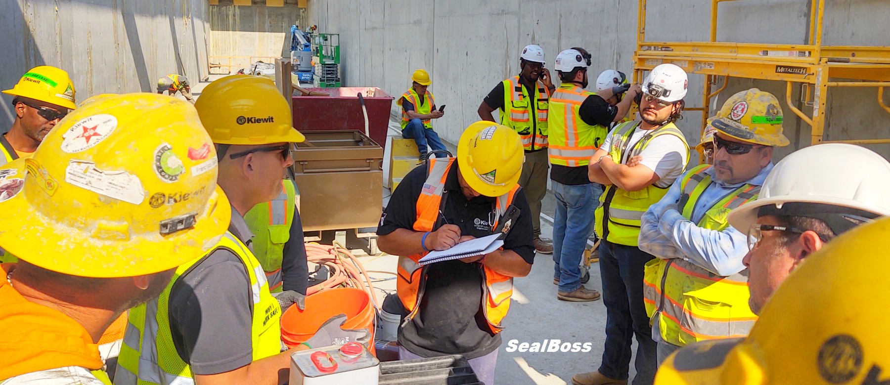
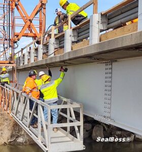
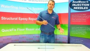
The article features a SealBoss field training session where construction professionals review crack-injection and leak-sealing procedures, equipment, and best practices at an active jobsite.

Built on Experience. Sealed for the Future. Since 1988.

Show the daily log instead of merely describing it

A field log should preserve observations without overstating what they prove. The exact fields may vary, but the following structure provides a practical starting point.

Point or stage Start Stop Product / batch Volume Observed pressure Returns / communication Water response Notes / deviation
B1-W3-P07 09:12 09:19 [Exact product / lot] [unit] [unit] Material observed at P08 Flow reduced at P07 Continued under approved sequence
B1-W3-P08 09:24 09:31 [Exact product / lot] [unit] [unit] Surface return at joint No visible change Paused; containment adjusted
B1-W3-P09 09:42 09:48 [Exact product / lot] [unit] [unit] None observed Area damp, no active drip Marked for follow-up

The sample entries illustrate format only. They are not performance criteria or field instructions.

“Material became visible at P08 while P07 was being injected” is an observation.

“The entire crack was completely filled” is a broader conclusion that may not be established by that return alone.

A decrease in water flow may show that the injection affected the active pathway. Increased resistance may reflect material reaction, restricted geometry, blockage, packer condition, or another factor. The field record should preserve the observable event first; interpretation belongs under the current guideline and the authority assigned by the project.

Verification under relevant service conditions

The field record should connect the pre-work condition, installed system, immediate observations, and later verification under relevant conditions.

The sample daily injection log remains in the article as an editable table. This field image supports the follow-up discussion and links to a related SealBoss application example.

View the SealBoss elevator-pit waterproofing article.

Track material consumption by a meaningful unit of work

Material consumption can support production tracking, scope review, and troubleshooting when it is tied to the treatment area.

A small crack project may record total use and the points treated. A larger program may track material by crack, joint, elevation, zone, grid area, stage, shift, or product batch.

Unexpectedly high or low consumption should be noted. Higher consumption may be associated with larger voids, travel beyond the anticipated area, uncontrolled discharge, or a broader treatment volume. Lower consumption may reflect restricted access, early resistance, smaller void volume, equipment interruption, or an incorrect assumption about the pathway.

Consumption alone does not establish repair quality. It becomes useful when evaluated with the point map, water observations, equipment record, material configuration, site conditions, and later inspection.

Record deviations and unexpected conditions

Injection work may reveal conditions that were not visible during the initial assessment.

A drill hole may fail to intersect the expected opening. Concrete may contain voids or embedded material. A packer may communicate with an unexpected joint. Material may emerge at a distant location. A previous repair may redirect flow. A formerly dry opening may begin discharging as the original pathway is restricted.

The deviation record should identify the location, observation, immediate action, person consulted, and any authorized change in scope or method. Where technical or engineering confirmation is required, the report should show that the relevant work was paused, limited, or redirected pending instruction.

A field adjustment should not disappear from the final report simply because the crew completed the work.

Use tiered verification appropriate to the original problem

Verification should become more structured as the consequence, uncertainty, and water condition increase.

Verification level Example method What it can support Important limitation
1. Visual observation Defined photographic intervals and repeatable viewpoints Documents visible change at the treated surface Does not quantify concealed flow or prove all pathways are addressed
2. Timed flow measurement Drops per minute or timed catch volume Compares discharge at the same point and condition Requires repeatable collection and comparable water load
3. Moisture-pattern comparison Moisture meter or thermal imaging Supports comparative mapping of damp areas Instrument and environmental limitations require interpretation
4. Water-level or pressure monitoring Piezometer, standpipe, or other approved instrument Tracks groundwater or behind-wall conditions Requires installation, baseline, and responsible technical interpretation
5. Controlled water test Flood, dye, or compartment test where authorized Tests communication or water-tightness under a defined condition May be unsuitable for occupied, sensitive, or uncontrolled structures
6. Service-condition verification Rain event, tank fill, operating cycle, or normal system load Evaluates the repair under the condition that produced the original leak Timing and water load may be difficult to reproduce exactly

The project team should establish the verification method, interval, acceptance basis, and responsible party before the work begins.

Describe the immediate result without promising the future

At the end of the injection sequence, the report can state whether active water stopped, decreased, moved, remained unchanged, or could not be evaluated under the conditions present. It may identify damp areas, open packer holes, surface finishing, material curing, remaining leaks, and locations requiring later observation.

“Area dry at the completion of the shift” is a time-specific observation.

“Leak permanently eliminated” is an unsupported future promise.

ASTM D8109-25 describes chemical-grout waterproofing as potentially iterative. The water source remains, flow can be diverted, and periodic monitoring or additional repair may be required depending on the conditions.

Distinguish workmanship, product warranty, and project water-tightness obligations

Owners frequently ask whether an injection repair is “warranted.” That question should be separated into the actual obligations created by the product terms, contractor agreement, specification, and project contract.

  • A manufacturer’s product warranty or disclaimer addresses the product under the exact authorized wording. Review the current SealBoss Limited Warranty / Disclaimer; do not paraphrase it into a broader promise.
  • A contractor workmanship warranty, when offered, is created by the contractor’s written agreement and should identify its scope, term, exclusions, and remedy.
  • A project water-tightness or performance obligation, when required, belongs in the contract documents and acceptance criteria established by authorized parties.

This article does not create a warranty or promise a water-tight outcome. Warranty language must be reviewed and approved by the authorized parties for the specific project.

Assemble a closeout package that reconstructs the work

A useful closeout package should allow the project team to understand what was done without relying on memory. It should contain the pre-work assessment, repair objective, governing documents, material and equipment identification, point map, daily logs, consumption records, deviations, photographs, immediate post-work condition, unfinished items, verification results, and follow-up requirements.

Larger projects may also require submittals, certificates, mockup records, inspection reports, training records, disposal documentation, test results, and owner-specific forms.

The closeout package does not replace the data sheet, SDS, application guideline, pump manual, specification, or professional judgment. It shows how those sources were connected to the actual work.

Use the SealBoss Injection Job Checklist, Field Reference Sheets, and Resource Page as navigation aids alongside the comprehensive technical documents.

GO DEEPER ON SEALBOSS.COM

Related articles, products, equipment, and technical resources

Use the links below to move from the educational framework to the relevant SealBoss application, product, equipment, case-study, or technical page.

SealBoss Injection Job Checklist

Pre-work and field-readiness reference.

Field Reference Sheets

Quick application-oriented field references.

Crack Injection Pressure

Additional context on pressure and field observations.

Pump and Equipment Support

Equipment documentation and technical support.

SealBoss Resource Page

Data sheets, SDS documents, guidelines, manuals, and case studies.

SealBoss Limited Warranty / Disclaimer

Current authorized warranty and disclaimer wording.

Frequently asked questions

At minimum, identify the point or stage, time, exact product and batch where required, material volume, observed pressure, visible returns, water response, notes, and deviations. Project documents may require additional fields.

No. It can demonstrate communication between observed points, but it does not reveal every internal branch, void, or connected pathway.

The interval depends on the original water condition, structure, service environment, project requirements, and ability to reproduce the water load. Inspection timing and acceptance criteria should be established by the responsible project parties.

Not automatically. Product terms, contractor workmanship obligations, and project water-tightness requirements are separate matters governed by their current written documents.


Use the completed record to support closeout, follow-up, and informed future work.

Current SealBoss technical documents remain controlling. Contact a qualified SealBoss technical representative when material, equipment, or application selection requires additional review.

Technical source direction: SealBoss sources control SealBoss product and equipment facts. ASTM, ICRI, ACI, OSHA, and other primary authorities provide independent industry or regulatory context within their stated scopes. Project-specific suitability, engineering decisions, warranties, and field procedures require the current controlling documents and authorized responsible parties.

Concrete Injection as a Complete System: Material, Pump, Packers, and Method

SPECIFIED & VERIFIED — PART 3 OF 4

Concrete Injection as a Complete System: Matching Material, Pump, Packers, and Method

The injection material cannot be selected responsibly without considering how it will be prepared, delivered, connected, controlled, cleaned, and documented.

SealBoss Corp.  •  Technical blog series  •  Technical review required before publication

Part 1
Part 2
Part 3
Part 4

Scope boundary

This part explains system interfaces and readiness. It does not replace current product data sheets, SDS documents, application guidelines, packer information, or pump manuals. Field documentation is addressed in Part 4.

The material does not reach the structure by itself

Concrete injection is sometimes discussed as if the resin performs the repair alone.

In practice, the material must move through a coordinated delivery system. It may need to be proportioned, mixed, accelerated, pumped, carried through hoses and valves, connected to a packer or port, introduced into a concealed pathway, observed during travel, and managed during interruption, shutdown, and cleaning.

Each component affects the others.

The material, pump, packer or port, coupler, hose, applicator, cleaner, preparation method, operator, training, and current technical documents should therefore be reviewed as one system.

Complete-system map

  1. Repair objective and site condition define what the system must do.
  2. Material family and exact product variation define preparation, reaction or cure behavior, viscosity, mixing, and cleaning requirements.
  3. Pump configuration defines ratio capability, pressure, output, power source, and material-contact components.
  4. Hoses, valves, mixers, couplers, and applicators carry and control the material.
  5. Packers or ports connect the delivery system to the structure.
  6. Preparation and drilling controls establish the intended pathway and protect embedded components.
  7. Cleaning, shutdown, safety, documentation, and training keep the system operable and traceable.

Begin with the repair objective and exact product variation

Water-control injection, structural epoxy crack repair, joint treatment, penetration sealing, void filling, and curtain injection involve different material behaviors and delivery requirements. Active water, damp or dry conditions, movement, defect geometry, expected volume, access, substrate and ambient temperature, and service environment may further affect the configuration.

The objective should be stated before the equipment list is prepared. That statement gives the contractor and technical representative a basis for reviewing material family, component configuration, viscosity, reaction or cure profile, required flow, pump category, injection-point type, connection method, and cleaning procedure.

Temperature deserves specific attention. Material temperature, substrate temperature, and ambient temperature may affect viscosity, reaction or cure speed, pot life, pressure response, and pump behavior. Exact limits and conditioning requirements must come from the current data sheet, application guideline, and equipment manual.

Without that sequence, the crew may arrive with components that are individually useful but not coordinated for the intended application.

Pump selection is part of material selection

A pump should not be selected only because it can generate pressure.

Injection performance depends on the relationship among component ratio, material viscosity, output volume, pressure, hose arrangement, seal and wetted-part compatibility, injection-point resistance, defect geometry, and the volume that must be delivered.

When comparing pumps, review at least these specification categories:

Pump specification Why it matters Controlling source
Component configuration and ratio Determines whether one or more material streams can be prepared and proportioned correctly. Exact product data sheet and pump manual
Maximum pressure Defines equipment capability, not the pressure that should be used on a particular structure. Pump manual and application guideline
Output volume or flow range Affects delivery for fine cracks, defined joints, higher-volume voids, or broad-area work. Pump manual
Power source Electric, pneumatic, hydraulic, or manual operation affects site logistics and controls. Pump page and manual
Material-contact components and seals Compatibility affects operation, cleaning, and maintenance. Pump manual and written technical confirmation
Hose and applicator arrangement Determines how material reaches the packer or port and how components are mixed where applicable. Pump manual and system documentation
Cleaning and shutdown requirements Must be planned before material enters the equipment. Current cleaning guidance, SDS, and pump manual

The SealBoss Pumps Overview, Leak-Seal and Crack-Injection Pumps, and Epoxy Injection Pumps pages organize the current equipment paths by application and material configuration. Model names, ratios, maximum pressure, output, material-contact components, current availability, and product-pump compatibility must be confirmed from the current product page and pump manual.

The existence of several pump platforms does not create a universal model-selection chart. It shows why the exact product and application must be matched to the current equipment documentation.

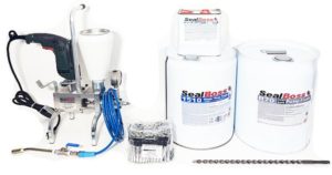
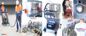
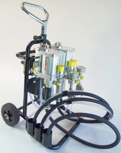
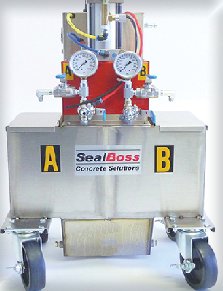
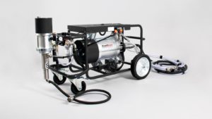
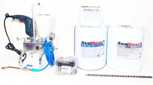
A coordinated product, pump, and packer system

Material, pump, injection points, hoses, connections, cleaner, and current technical documents must be reviewed as one system.

The image provides a practical system overview. Exact product-pump compatibility and operating requirements remain controlled by the current data sheet, application guideline, and equipment manual.

Browse SealBoss injection pumps and system resources.

Pressure and flow describe different parts of the injection

Pressure is often emphasized because it can be observed on a gauge. It does not, by itself, describe material travel or repair completeness.

The reading may be influenced by material viscosity, temperature, hose length, valve restriction, pump configuration, packer condition, crack geometry, concrete density, blockage, elevation, reaction, and resistance within the treatment path.

Flow, material consumption, visible returns, leakage at the surface, and changes in water discharge provide additional information. None should be interpreted in isolation.

A rising pressure does not automatically prove that a crack is filled. Material appearing at an adjacent point may show communication between two locations, but it does not reveal every branch or void. A reduction in water flow indicates a change in the active pathway; it does not establish that every connected path has been addressed.

Review Crack Injection Pressure for the broader explanation, then follow the current application guideline and pump manual for the exact system.

Packers or ports are the interface with the structure

The packer or port connects the delivery equipment to the repair pathway.

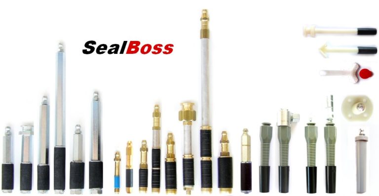
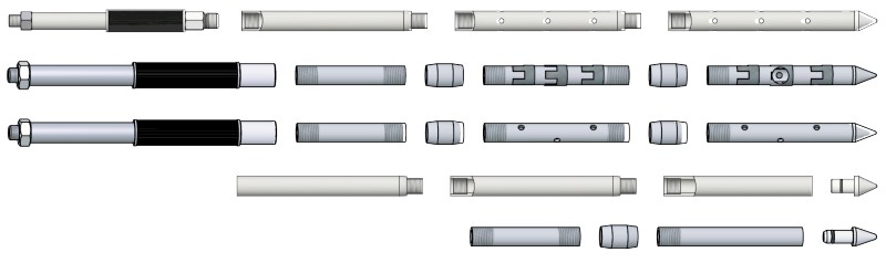
SealBoss provides mechanical packers, hammer-in ports, surface-mounted ports, epoxy ports, button-head configurations, Zerk fittings, couplers, needles, and injection lances. The current Injection Packers, Ports, and Couplers page and Packer Overview should be used to verify exact dimensions and connections.

A useful packer comparison starts with the categories below. Values are intentionally omitted from this article because they must be taken from the current product source.

Selection field What the reader should verify
Packer or port type Mechanical, hammer-in, surface-mounted, epoxy port, needle, lance, or other approved category
Diameter Exact outside diameter and compatible drilled opening
Drill-bit size Current requirement for the selected packer and substrate condition
Length Reach, anchorage, wall geometry, and access
Body material Steel, brass, aluminum, zinc, plastic, or another listed material
Head type Zerk, button-head, or other connection
Coupler and hose interface Secure match to the delivery system
Check-valve or anti-return arrangement Current product configuration and intended control
Removal or finishing requirement Project and application-specific closeout

A packer should not be treated as a minor consumable chosen after the pump arrives. It determines how the equipment connects to the structure and how material delivery is controlled at the injection point.

Go deeper: Review Injection Packers, Ports, and Couplers, Injection Needles, Injection Lances, and Hoses, Applicators, Accessories, and Parts.

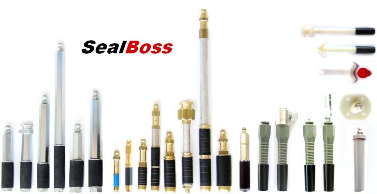
Mechanical packers and surface ports

Injection-point selection coordinates anchorage, diameter, length, fitting type, coupler compatibility, access, and the applicable method.

The current SealBoss Packer Overview and individual product pages should be used to confirm dimensions, connection type, and application limitations.

View SealBoss injection packers, ports, and couplers.

Hoses, valves, couplers, mixers, and applicators complete the delivery path

The components between the pump and the packer or port are part of the operating system.

The hose must suit the equipment, material, connection arrangement, and intended operating conditions. Valves and control devices must be compatible with the selected material and pump. The coupler must attach securely to the injection point. Static mixers, anti-return arrangements, applicators, extensions, and other components may be required for particular multicomponent or access conditions.

Every added connection introduces another point that must be inspected, assembled, operated, depressurized, and maintained under the approved procedure.

A coupler that does not match the head can stop production or lead to improvised adapters. An unsuitable hose or valve may create unnecessary restriction. A damaged seal can allow leakage. A worn connection may make it difficult to control disconnection and movement between points.

Review the entire delivery path before the material enters the pump.

Scan before drilling and define the intended pathway

Even a compatible material and equipment package cannot compensate for an undefined target.

The crew should understand what each point is intended to reach, how the area will be prepared, how embedded components will be avoided, how uncontrolled discharge will be contained, and how the sequence relates to defect geometry.

Available drawings and construction records should be reviewed first. Where the risk and project conditions justify it, ground-penetrating radar, electromagnetic or magnetic rebar locators, cover meters, or other non-destructive evaluation methods may help identify reinforcement, conduits, post-tensioning components, and embedded objects before drilling. FHWA guidance on ground-penetrating radar describes its use for mapping reinforcement and other subsurface features; ACI PRC-228.2-13 provides broader industry context for non-destructive test methods.

These tools have limitations. Scanning should be planned and interpreted by qualified personnel, and it does not replace drawings, utility-location procedures, or project-specific restrictions.

Detailed drill angle, depth, spacing, and preparation must come from the current SealBoss application guideline or approved project method statement.

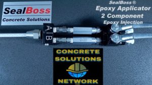
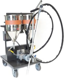
Delivery components for plural-component systems

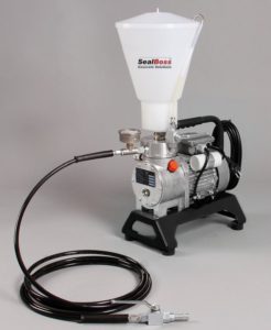
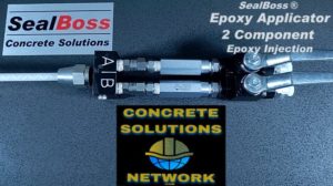
Hoses, valves, applicators, anti-return components, static mixers, and couplers form part of the material-delivery system.

This equipment image is used in place of an unapproved drilling diagram. Drilling angle, offset, depth, and spacing must be taken from the current application guideline rather than inferred from a generic illustration.

Review SealBoss hoses, applicators, and accessories.

Safety and compliance belong in the readiness review

System readiness includes the work environment, not only the equipment cart.

Concrete drilling may generate respirable crystalline silica. OSHA 29 CFR 1926.1153 includes Table 1 controls for specified equipment and tasks, including handheld and stand-mounted drills. Employers must determine the applicable controls, exposure assessment, respiratory protection, housekeeping, training, and written-plan requirements for their work.

Injection may also occur in pits, tanks, vaults, manholes, and similar spaces. OSHA 29 CFR 1926 Subpart AA addresses confined spaces in construction. Tunneling work may instead fall under 29 CFR 1926 Subpart S, and the regulatory scope should be evaluated by the employer and responsible safety personnel.

Product hazards, handling, exposure controls, and personal protective equipment must come from the current SDS and approved safety documentation. This article does not replace a site-specific safety plan or regulatory assessment.

Cleaning and shutdown must be planned before injection starts

Reactive, curing, or adhesive materials may remain in pumps, hoses, mixers, valves, applicators, and couplers after use.

The required cleaner, conditioner, water flush, solvent, timing, disassembly, storage, waste handling, and restart procedure depend on the exact product and equipment configuration. Those instructions must come from the current product information, SDS where applicable, SealBoss cleaning guidance, and pump manual.

The SealBoss Resource Page links to pump information, SDS documents, technical documents, and SealBoss R70 Pump Flush. The crew should review cleaning before material enters the system and have the required materials, collection containers, tools, and replacement components at the work area.

A system that can be started but cannot be cleaned correctly is not ready for professional operation.

Field context: one documented system, not a universal specification

The Hollow-Core Concrete Slab Water Leak Repair case study identifies SealBoss 1510 Water Stop Foam with accelerator, SealBoss aluminum mechanical packers, a SealBoss P2002 single-component injection pump, SealBoss R70 Pump Flush, and supporting drilling and inspection equipment.

The project demonstrates a complete-system sequence:

  1. The condition and concealed cells were investigated.
  2. The treatment area and water-control objective were defined.
  3. A named material and accelerator were documented.
  4. A pump and packer system were identified.
  5. Cleaning materials and supporting tools were planned.
  6. The work and follow-up recommendations were recorded.

The case study is not a universal specification. Current data sheets, packer information, manuals, guidelines, and project conditions must control any future selection.

Training makes concealed behavior easier to understand

Injection work involves material movement that is difficult to understand from product descriptions alone.

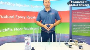
Hands-on training can allow contractors to observe drilling, packer placement, material preparation, pump operation, material travel, reaction behavior, connection changes, cleaning, and shutdown. Cut-away or transparent demonstrations can make otherwise concealed movement visible and help crews understand why similar gauge readings or returns may have different meanings under different conditions.

Review SealBoss Training and Certification for current program information. Training supports the technical documents; it does not replace them.

Complete-system readiness review

Before mobilization, confirm that:

  • The repair objective and treatment area are documented.
  • The exact material and variation are identified from current sources.
  • The pump is appropriate for the component configuration, ratio, pressure capability, output, seals, hoses, and cleaning requirements.
  • The packer or port, drill-bit requirement, head type, coupler, hose, and applicator are coordinated.
  • Embedded-component scanning and drilling restrictions have been addressed.
  • Substrate, material, and ambient temperatures are within the controlling documents.
  • Current data sheets, SDS documents, application guidelines, and pump manuals are available.
  • Cleaning, shutdown, waste, silica, confined-space, and site-safety requirements have been planned.
  • Operators understand the method and know when technical support is required.

This review is the point at which separate products and equipment become a workable injection system.

GO DEEPER ON SEALBOSS.COM

Related articles, products, equipment, and technical resources

Use the links below to move from the educational framework to the relevant SealBoss application, product, equipment, case-study, or technical page.

SealBoss Pumps Overview

Browse pump families by application category.

Leak-Seal and Crack-Injection Pumps

Pump pathways for water-stop and crack-injection work.

Injection Packers, Ports, and Couplers

Mechanical packers, ports, connections, and accessories.

Hoses, Applicators, Accessories, and Parts

Complete the delivery path from pump to injection point.

Pump and Equipment Support

Equipment service and support resources.

SealBoss Training and Certification

Hands-on product and equipment training.

Frequently asked questions

Maximum pump pressure is an equipment capability. Appropriate field pressure depends on the exact material, pump, structure, pathway, packer or port, application guideline, and observed response.

Review component ratio, maximum pressure, output volume or flow, power source, material-contact components, seal compatibility, hose and applicator arrangement, and cleaning requirements.

The team should verify packer or port type, diameter, drill-bit size, length, body material, head type, coupler, check-valve arrangement, substrate condition, access, and current application guidance.

Reactive or curing materials can remain in equipment and hoses. The correct cleaner, timing, disassembly, shutdown, and restart procedure depend on the exact material and pump system.


Confirm the system, then establish the field record and verification plan before mobilization.

Current SealBoss technical documents remain controlling. Contact a qualified SealBoss technical representative when material, equipment, or application selection requires additional review.

Technical source direction: SealBoss sources control SealBoss product and equipment facts. ASTM, ICRI, ACI, OSHA, and other primary authorities provide independent industry or regulatory context within their stated scopes. Project-specific suitability, engineering decisions, warranties, and field procedures require the current controlling documents and authorized responsible parties.

Crack, Joint, Penetration, or Broad-Area Leak? Choosing an Injection Approach

SPECIFIED & VERIFIED — PART 2 OF 4

Crack, Joint, Penetration, or Broad-Area Leak? Choosing an Injection Approach

The repair approach should follow the geometry of the water path, the available access, and the intended function of the repair.

SealBoss Corp.  •  Technical blog series  •  Technical review required before publication

Part 1
Part 2
Part 3
Part 4

Scope boundary

This part compares repair categories and material-family vocabulary. It does not prescribe a project-specific grout, drill layout, pressure, packer spacing, or equipment setup. Structural crack repair is outside the series.

The repair approach should follow geometry, access, and function

A leaking concrete structure is not one uniform repair condition.

Water may be moving through a discrete crack, along a construction joint, around a penetration, through a localized void, or across a broad area behind the structure. Each condition presents a different access problem. Each affects how packers or ports may be installed, where material is intended to travel, how the work can be observed, and which limitations must remain explicit.

The correct early question is not, “Which grout should be used?”

It is, “What are we trying to reach, and what is the repair expected to accomplish?”

Quick method-selection matrix

Condition Geometry and access Typical injection-point category Governing SealBoss path Explicit boundary
Discrete crack Traceable or intersectable opening through concrete Mechanical packer or surface port, as directed by the current guideline Polyurethane crack injection and epoxy versus polyurethane Waterproofing injection is not automatically structural repair.
Construction or cold joint Interface between placements; may continue beyond visible leak Packer, port, or existing designed injection system, as applicable Cold-joint resources and Resource Page Do not treat an expansion or movement joint as a construction joint without project review.
Pipe penetration or annular space Multiple possible interfaces around pipe, sleeve, seal, and surrounding concrete Localized packers or ports; oakum or backer material may be part of an approved containment method Watertight pipe penetration sealing and SealBoss Seal Oakum The visible wet ring does not prove which interface is carrying water.
Tie hole or localized void Recognizable opening or irregular local cavity Packer, port, needle, or other approved access Injection packers, ports, and couplers Extensive honeycombing or deterioration may require a broader repair scope.
Broad-area or blind-side infiltration Distributed pathways behind the structure or membrane Staged grid, high-volume packer, lance, or compartment access, as designed Curtain Injection in Pictures and blind-side waterproofing injection Curtain grouting is a separate application category, not simply “more crack injection.”

The table is a navigation aid, not a specification. Exact product, packer or port, drill layout, equipment, and application requirements must come from the current SealBoss source for the selected method.

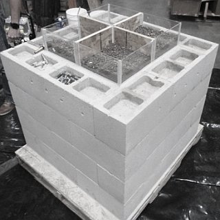
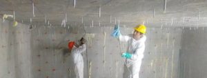
Field context: seeing the concealed side

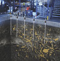
A training section makes material travel behind the wall visible and helps distinguish broad-area treatment from a discrete crack repair.

The photograph does not replace the method-selection table. It provides field context for why defect geometry and access should be established before a material or pump is chosen.

Explore SealBoss curtain-injection resources.

Begin with the pathway geometry

Injection introduces material into a crack, joint, opening, cavity, or treatment zone. The geometry of that destination matters before product chemistry is discussed.

A discrete crack may be traceable along a wall or slab. A construction joint may continue beyond the visible leak. A penetration may contain several interfaces within a small area. Broad seepage may indicate that no single visible opening represents the complete water path.

ICRI 710.5-2024, Guide for the Selection of Grouts to Control Water Leakage Through Cracks in Concrete Structures, provides independent industry context for relating grout characteristics to leakage-control conditions. The current designation and title should be cited in full on first use. Its scope does not make it a SealBoss product-selection document.

Discrete cracks: water control or structural repair?

A defined crack is often the most recognizable injection condition, but its internal geometry is rarely visible.

The surface expression may be continuous or intermittent, fine or open, dry or actively leaking. The crack may pass through the concrete element, branch internally, intersect another crack or joint, or terminate before reaching the opposite face.

Before crack injection is selected, the project team should consider whether the crack can be traced, whether water activity is present, whether movement is suspected, whether the concrete can support the intended injection point, and whether the repair objective is water control or structural crack bonding.

Those objectives must remain distinct.

ASTM D8109-25, Standard Guide for Waterproofing Repair of Concrete by Chemical Grout Crack Injection, addresses chemical-grout injection as a waterproofing repair and excludes injectable materials used for structural repair. ACI RAP-1, Structural Crack Repair by Epoxy Injection, addresses structural epoxy crack repair as a separate professional task.

The existing SealBoss comparison, Epoxy Versus Polyurethane Crack Injection, is the appropriate deeper path for readers comparing those repair objectives. The current data sheet and project requirements must control any named product selection.

Construction joints, cold joints, and movement joints are not interchangeable

A construction or cold joint is an interface created by the sequence or condition of concrete placement. It may extend beyond the visible wet area and intersect waterstops, keyways, penetrations, wall-to-slab interfaces, or other construction details.

An expansion or movement joint is intentionally detailed to accommodate movement. Injection that rigidly or indiscriminately fills the joint may interfere with its intended function. The project team should confirm the joint type, movement requirement, seal or waterstop configuration, and repair objective before selecting a method.

A localized injection approach may be considered when the relevant pathway can be reached and contained. Where a preplaced injection tube is part of the original joint system, the manufacturer’s current instructions and project documents control its use. ASTM D8109-25 specifically excludes injection into preplaced permeable waterstop tubes from its scope; those systems should not be presented as though they fall under the guide’s crack-injection procedure.

The visible leak length should not automatically define the complete treatment length. Nor should one drill pattern or packer spacing be applied to every joint without the current SealBoss guideline and project review.

Pipe penetrations and annular spaces contain several possible pathways

Water around a pipe, conduit, sleeve, tie, anchor, or embedded component may travel through the annular space, along the outside of the sleeve, through a failed seal, through adjacent cracked concrete, or beside another embedded interface.

The project team should establish what components are present, where they extend, and which spaces must remain open. Drawings, utility records, and information about the original penetration assembly can be especially important.

A localized injection approach may be suitable when the pathway is defined and the intended material destination is acceptable. Wider or irregular openings may require an approved containment method using oakum, backer material, or another compatible support component before or during injection. The exact method must come from current SealBoss application guidance.

Review Watertight Pipe Penetration Sealing, SealBoss Seal Oakum, and the SealBoss Resource Page for the relevant technical path.

Penetration repair components

Penetration repairs may involve the pipe, sleeve, annular space, adjacent concrete, containment material, and the intended destination of the injected material.

This product photograph is linked as a resource pathway; it is not a universal penetration specification. Confirm the assembly and current application guidance for the actual condition.

View the SealBoss Seal Pipe Kit.

Tie holes, honeycombing, and localized voids

Tie holes and localized construction defects can create direct or interconnected water pathways.

Some form-tie openings are readily recognizable. Others may be concealed by patching or finishes. Honeycombed concrete may contain a network of irregular voids rather than one smooth passage.

When the condition appears localized and the opening can be reached, a defined injection or sealing approach may be considered. When the defective area is extensive, deteriorated, or structurally significant, a broader repair assessment may be required.

The team should not assume that water emerging from one tie hole is confined to the original tie diameter. The scope should reflect the apparent volume and continuity of the defect—not merely the size of the visible outlet.

Broad-area seepage and inaccessible positive-side conditions

Some structures exhibit distributed dampness, recurring seepage at several points, multiple fine leaks, or evidence that water is moving across the positive side of the structure.

When positive-side access is unavailable, treatment of each visible outlet may not address the broader condition. Curtain, bladder, blanket, stage-grouting, compartment, or related area-injection concepts may warrant evaluation.

This is a different repair geometry from crack injection. Crack injection seeks to reach an identified opening within the concrete. Curtain-type work introduces material through the structure into a treatment zone behind or adjacent to it. The work may require a grid or staged layout, different flow characteristics, greater material volume, high-volume packers, specialized pumps, mockups, and more extensive monitoring.

Section 4.6 of ASTM D8109-25 identifies existing construction, prior waterproofing installations, access, water volume or flow rate, water chemistry, temperature, humidity, and other factors as conditions that may warrant evaluating curtain grouting as an alternative to crack injection.

Go deeper: See Curtain Injection in Pictures, Blind-Side Waterproofing Injection, SealBoss Injection Lances, and the curtain layout resources on the Resource Page.

Curtain injection as a separate application category

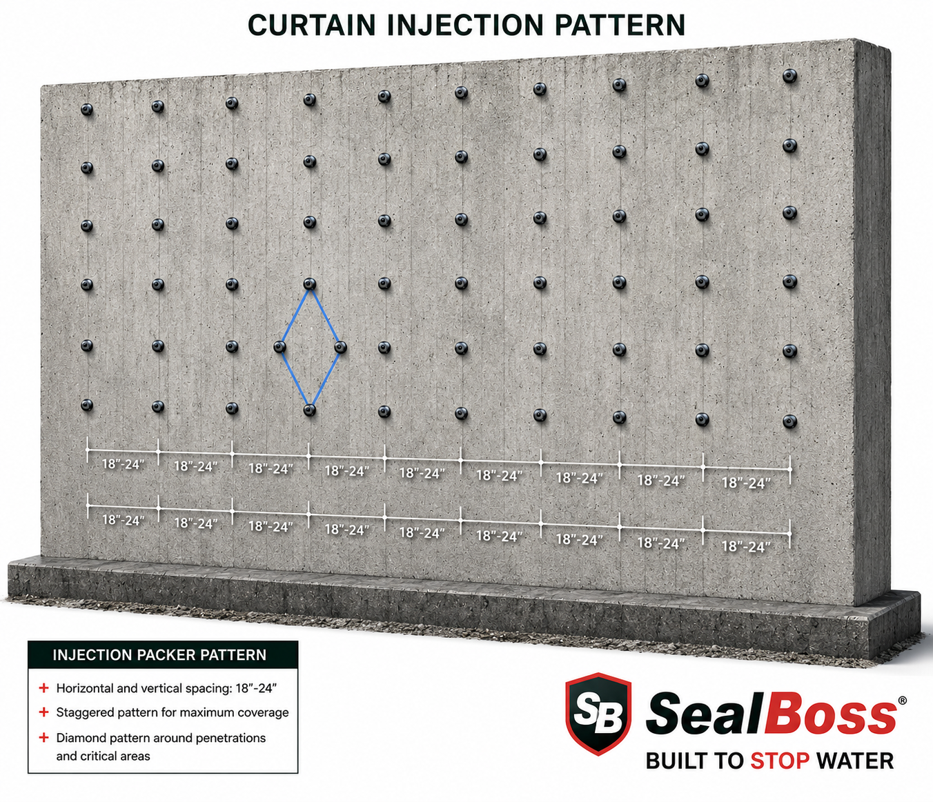
SealBoss Curtain Injection Pattern
Curtain-type work creates a broader treatment zone behind or adjacent to the structure rather than treating one identified opening within the concrete.

The photograph supports the broad-area section of this article. Detailed grid layout, material selection, equipment, and injection sequence must come from current SealBoss guidance and project-specific review.

See curtain injection in pictures.

Material families at a glance

This block provides vocabulary, not a project-specific selection rule.

Material family or configuration General distinction SealBoss reading path
Hydrophobic polyurethane Water-reactive polyurethane category in which the cured material is generally intended to resist water uptake; products may form foam or resin-like structures depending on formulation. Hydrophobic Versus Hydrophilic Polyurethanes and SealBoss 1510 Water Stop Foam
Hydrophilic polyurethane Polyurethane category formulated to interact strongly with water and, depending on the product, form flexible foam or gel. Hydrophobic Versus Hydrophilic Polyurethanes and SealBoss FlexGel
Single-component configuration One principal resin stream is delivered by the pump; an accelerator or additive may be incorporated before pumping when the exact product requires it. Current product data sheet, application guideline, and leak-seal pump category
Plural-component configuration Components are kept separate and proportioned or mixed through the approved equipment arrangement. SealBoss 2400 Acrylate Gel and current gel-pump documentation
Foam Material response includes expansion or foaming; the exact expansion, cell structure, reaction profile, and confinement requirements are product-specific. Water Stop–Leak Seal overview
Gel Material forms a gel rather than a conventional expanding foam; viscosity, reaction, flexibility, water interaction, and service limits are product-specific. SealBoss FlexGel and SB 2400 Acrylate Gel
Epoxy Rigid adhesive resin category used for structural crack bonding when the crack, substrate, design, and installation conditions are appropriate. Structural Repairs–Epoxy and Epoxy Injection Structural Concrete Repairs

Exact properties and suitability must be verified from the current SealBoss data sheet, application guideline, certification, and project documents.

Site conditions may require testing or a mockup

Some projects contain factors that cannot be resolved adequately from a general comparison. Water chemistry, contamination, unusual temperature, unknown void geometry, nearby buried components, existing membranes, occupied conditions, and environmental restrictions may affect material selection or containment planning.

Any SealBoss chemical-resistance, compatibility, or exposure statement must come from the current SealBoss data sheet, resistance chart, test report, or written technical confirmation.

Select the repair category before assembling the system

Use this sequence:

  1. Document the condition.
  2. Identify the apparent geometry.
  3. Define the repair objective.
  4. Confirm access, material destination, and limitations.
  5. Select the repair category.
  6. Review the current material, pump, packer or port, accessories, guideline, cleaning, safety, and training requirements.

There is no responsible one-line rule that selects a complete injection system from the visible defect name alone.

GO DEEPER ON SEALBOSS.COM

Related articles, products, equipment, and technical resources

Use the links below to move from the educational framework to the relevant SealBoss application, product, equipment, case-study, or technical page.

Concrete Crack Injection—Polyurethane

Dedicated polyurethane crack-injection overview.

Epoxy Versus Polyurethane

Compare water-control and structural-repair objectives.

Cold Joint Injection

Application context for leaking concrete joints.

Watertight Pipe Penetration Sealing

Penetration and annular-space context.

Curtain Injection in Pictures

Visual overview of broad-area blind-side treatment.

Blind-Side Waterproofing Injection

Additional inaccessible positive-side context.

Frequently asked questions

No. Chemical-grout waterproofing and structural epoxy crack repair have different objectives, material behavior, equipment, and project responsibilities. Review Epoxy Versus Polyurethane Crack Injection and the current technical documents for the exact system.

Not automatically. An expansion or movement joint is intended to accommodate movement. Its design, seal or waterstop system, movement requirement, and repair objective must be reviewed before injection is selected.

Curtain injection may warrant evaluation when water paths are distributed behind the structure, positive-side access is unavailable, or project factors make individual crack injection insufficient. The decision requires project-specific review and current application guidance.

No. The visible location is only one factor. The repair objective, water condition, defect geometry, access, movement, service environment, material destination, and delivery system also matter.


Translate the selected repair category into a coordinated material, pump, packer or port, and method.

Current SealBoss technical documents remain controlling. Contact a qualified SealBoss technical representative when material, equipment, or application selection requires additional review.

Technical source direction: SealBoss sources control SealBoss product and equipment facts. ASTM, ICRI, ACI, OSHA, and other primary authorities provide independent industry or regulatory context within their stated scopes. Project-specific suitability, engineering decisions, warranties, and field procedures require the current controlling documents and authorized responsible parties.

Concrete Leak Assessment Before Injection

SPECIFIED & VERIFIED — PART 1 OF 4

Before Concrete Leak Injection: Assessing Water Infiltration and Repair Conditions

A useful injection plan begins with a clear description of the structure, the water condition, and the repair objective—not with a product name.

SealBoss Corp.  •  Technical blog series  •  Technical review required before publication

Part 1
Part 2
Part 3
Part 4

Scope boundary

This part covers assessment and documentation before selection. Method selection is addressed in Part 2; system configuration is addressed in Part 3.

A visible leak is the beginning of the assessment—not the complete diagnosis

Water emerging from a concrete wall, slab, ceiling, or joint is an observable condition. It does not necessarily identify where the water entered, how far it traveled, or which opening through the structure is carrying it.

That distinction matters because injection work is performed largely within pathways that cannot be seen directly. A contractor may observe a wet crack, a leaking joint, staining around a penetration, or broad dampness across a wall. The water may be moving through the visible opening, but it may also have traveled along another crack, joint, embedded component, void, membrane interface, or poorly consolidated area before reaching the accessible surface.

For contractors, engineers, owners, and facility managers, the first task is not to select a resin. It is to establish what is known, what is suspected, and what still requires investigation.

Quick assessment snapshot

Record before selection Why it matters
Visible discharge location and wetted area Defines the symptom that can be observed and mapped.
Water activity and trigger Separates dry, damp, intermittent, and active conditions.
Apparent defect category Helps distinguish cracks, joints, penetrations, localized voids, and broad seepage.
Access and surrounding construction Affects the practical repair category and the acceptable destination of injected material.
Previous repairs Earlier ports, patches, or injections may alter access and redirect water.
Movement or distress indicators May require structural evaluation separate from waterproofing injection.
Repair objective Prevents water control, structural bonding, joint treatment, and broad-area grouting from being conflated.

The visible leak is an observation, not yet a diagnosis

Water generally follows the path that offers the least resistance. In concrete construction, that path may involve shrinkage cracks, construction joints, control joints, pipe penetrations, tie holes, voids, honeycombed concrete, interfaces between materials, or defects in an existing waterproofing system.

The point where water becomes visible may be easier for the water to exit than the point where it entered. A wet floor-to-wall joint may be receiving water from an adjacent wall crack. Moisture surrounding a pipe may be traveling through the annular space, along the outside of a sleeve, through cracked concrete, or beside another embedded component. Several apparently separate leaks may also be connected to one broader water source.

ASTM D8109-25, Standard Guide for Waterproofing Repair of Concrete by Chemical Grout Crack Injection, explains that injection obstructs infiltration at a particular location but does not eliminate the source of the water. The guide also recognizes that water may be diverted and later appear elsewhere. This is why assessment and follow-up belong to the repair process rather than being treated as administrative extras.

A responsible assessment distinguishes among:

  • Direct observations: what can be seen, measured, photographed, or traced.
  • Reasonable inferences: what the construction and leak pattern suggest.
  • Unconfirmed conditions: what still requires records, testing, exploratory work, or professional judgment.

Classification should not harden into false certainty. “Water is visible along 8 ft of the floor-to-wall interface” is a defensible observation. “All water is entering through that joint” is a broader conclusion that may require additional support.

Visible leakage is the starting point

Parking Garage Crack Injection Leak-Seal Repair
A visible leak identifies where water appears; assessment must still consider how it reached that location.

The visible discharge point should be documented in the context of the surrounding construction, drainage, joints, cavities, and previous repairs.

Read the hollow-core slab case study.

Establish a measurable baseline before the condition changes

The repair area should be documented before drilling, cleaning, patching, removing finishes, or installing packers or ports.

Photographs should establish the location and extent of the observed condition. A simple elevation, plan, marked photograph, or field sketch can show cracks, joints, penetrations, staining, efflorescence, corrosion marks, previous repairs, and active discharge points. The record should identify whether the area is dry, damp, intermittently wet, steadily leaking, or carrying a more substantial flow at the time of observation.

Descriptive terms become more useful when paired with a measurement. Depending on the site and responsible project requirements, the record may include:

  • Drops per minute at a discrete leak.
  • Timed catch volume, such as milliliters or gallons collected over a stated period.
  • Wetted length or area, measured in feet or square feet.
  • Estimated water head or a measured water level where that information is available.
  • The rainfall, tank level, operating cycle, groundwater condition, or other event associated with the leak.

The goal is not false precision. It is repeatability. A later inspection is more meaningful when it can compare the same location under a similar condition.

Use investigation tools according to the question being asked

No single instrument reveals the complete water path. Investigation tools should be selected for a specific purpose and interpreted within their limitations.

A crack comparator card can help record visible crack width at the surface. Crack monitors or tell-tales observed over a temperature or operating cycle can help document movement, but they do not establish structural adequacy. Moisture meters can support comparative readings when the substrate and instrument are understood; they should not be treated as direct maps of concealed water movement. Thermal imaging can help identify temperature patterns associated with moisture, voids, or air movement, but the image requires interpretation and suitable environmental conditions.

A borescope may provide a view into a hollow core, cavity, drilled opening, or concealed space. Dye testing and controlled flood testing may help establish communication between locations when the structure, finishes, drainage, environmental conditions, and project authority permit them. Piezometers can record water levels or pressure conditions in soil or behind a structure when a project requires subsurface monitoring.

The tool should follow the question. The resulting observation should be recorded without claiming more than the method can establish.

Go deeper: Review Types of Concrete Cracks and Leak Sealing Methods before assigning a visible condition to an injection category.

Examine the structure beyond the wet surface

The immediate repair area should be reviewed in the context of the surrounding construction.

Relevant questions include whether positive-side access is available, whether exterior drainage is functioning, whether an original membrane or waterstop is present, whether the element is cast-in-place concrete, shotcrete, precast construction, masonry, or a combination, and whether utilities or sensitive spaces are located behind the treatment area.

The structure’s geometry can influence water movement. Hollow-core slabs, cavities, beam pockets, construction joints, and embedded sleeves may allow water to travel farther than expected. A wet point on the interior surface may therefore be only one location within a larger network.

SealBoss field context — water held within concealed cells: In the Hollow-Core Concrete Slab Water Leak Repair case study, interior dripping was considered together with exterior drainage and water held within concealed slab cells. A borescope was used to examine the suspected area. The project illustrates why the visible discharge point should be treated as the beginning of the assessment, not the complete diagnosis.

The lesson is not that every hollow-core leak requires the same method. It is that the investigation should extend beyond the point where water happens to emerge.

Field context: hollow-core slab investigation

The documented project connected visible interior leakage with exterior drainage and water held within concealed slab cells.

The project illustrates why leak assessment may involve exterior conditions, concealed cavities, inspection tools, injection equipment, and later monitoring rather than the wet surface alone.

Open the full SealBoss project record.

Review previous repairs as part of the current condition

Earlier work can reveal useful information about the history of the leak.

Surface patches, coatings, sealants, abandoned drill holes, cut-off ports, previous injection points, repaired joints, and localized demolition may show where water was previously observed and which methods were attempted. They may also have changed the present pathway.

A patch may conceal a crack while water appears nearby. A completed injection may reduce flow at one location and make another connected opening more visible. Repeated repairs along the same joint may indicate a larger treatment area, continuing movement, limited access, or incomplete understanding of the water source.

Previous work should not automatically be described as unsuccessful. It should be documented neutrally. Where available, collect the earlier contractor’s report, product identification, photographs, repair dates, drawings, and follow-up observations.

Determine whether movement or structural distress requires separate evaluation

A leaking crack should not automatically be treated as a waterproofing problem alone.

Displacement across the crack, continuing movement, unusual width, recurring cracking beside earlier repairs, significant spalling, corrosion staining, exposed reinforcement, loss of section, changes in alignment, or other signs of deterioration may require evaluation by a qualified design professional.

ACI PRC-224.1-07, Causes, Evaluation, and Repair of Cracks in Concrete Structures, provides industry context for evaluating crack causes and selecting repair approaches. It does not replace a project-specific structural assessment.

A practical movement record may include dated width measurements, a crack monitor, photographs with a fixed scale, and observations over temperature or operating changes. These methods document change; they do not determine structural adequacy.

ASTM D8109-25 also states that cracks in below-grade concrete walls may indicate structural distress and that the overall condition should be assessed before a nonstructural waterproofing repair is selected.

Define the repair objective in practical terms

Concrete injection can serve different purposes, and those purposes should not be conflated.

The objective may be to control active water infiltration, seal a leaking crack or joint, treat an annular space around a penetration, fill a localized void, address a damaged membrane compartment, or create a broader treatment zone behind an inaccessible surface. Structural crack repair by epoxy injection represents a separate objective and should be addressed under the appropriate engineering and technical framework.

The project record should state what the work is intended to accomplish and what lies outside its scope. “Control active water entering through the documented floor-to-wall joint within the designated treatment area” is more useful than “waterproof the basement,” which may imply responsibility for conditions beyond the observed joint.

A clear objective allows the project team to identify the relevant application guideline, material family, pump category, packer or port system, inspection method, and follow-up requirement.

Consider access and the intended destination of the material

Positive-side access allows the water-bearing face to be evaluated directly. Negative-side work begins from the opposite, accessible face.

Negative-side injection can reach a crack, joint, opening, or space through the structure, but the intended destination of the material must still be understood.

The team should consider what lies behind the concrete and where injected material is permitted to travel. Adjacent property, occupied areas, drains, utilities, process equipment, waterways, membranes, soil, cavities, and finishes may all affect containment and method selection.

Section 4.6 of ASTM D8109-25 identifies existing construction, prior waterproofing installations, access, water volume or flow rate, water chemistry, temperature, humidity, and other factors as conditions that may warrant evaluating curtain grouting as an alternative to crack injection.

That decision is project-specific. Continue to Part 2: Choosing an Injection Approach for a geometry-based comparison of cracks, joints, penetrations, and broad-area conditions.

Build an assessment record that supports the next decision

A useful pre-injection record should allow another qualified person to understand the condition without relying entirely on a verbal explanation. It should identify the structure and exact treatment area; show cracks, joints, penetrations, and leak points; describe current and reported water activity; note previous repairs; record access limitations; and state the repair objective.

Available construction details—wall thickness, joint locations, waterstops, membranes, drainage components, embedded utilities, and adjacent occupied areas—should be included when relevant. Unknown wall thickness, concealed construction, inability to reproduce the reported leak, or incomplete information about prior repairs should be stated openly.

Uncertainty is not a failure of the assessment.

Unrecorded uncertainty is the problem.

GO DEEPER ON SEALBOSS.COM

Related articles, products, equipment, and technical resources

Use the links below to move from the educational framework to the relevant SealBoss application, product, equipment, case-study, or technical page.

Water Infiltration Costs & Injection Grouting

Problem context and consequences of unmanaged infiltration.

Leak Sealing Methods

Broader overview of SealBoss leak-sealing approaches.

Types of Concrete Cracks

Additional crack terminology and context.

SealBoss Injection Job Checklist

Jobsite preparation and readiness reference.

Field Reference Sheets

Visual field references for injection applications.

Hollow-Core Slab Case Study

Documented assessment of visible leakage and concealed cells.

Frequently asked questions

Not necessarily. It identifies where water is visible at the time of observation. Water may have traveled through connected cracks, joints, cavities, penetrations, or interfaces before reaching that point.

Depending on the question, tools may include crack comparator cards, crack monitors, moisture meters, thermal imaging, borescopes, controlled dye or flood testing, timed flow measurements, and piezometers. Each method has limitations and should be selected and interpreted by the responsible project personnel.

Displacement, continuing movement, significant deterioration, corrosion, exposed reinforcement, alignment changes, or other signs of distress may require evaluation by a qualified design professional before the condition is treated only as a waterproofing repair.

Record the location, leak activity, wetted area, defect geometry, access, prior repairs, known construction details, repair objective, measurements, photographs, and unresolved conditions.


Use the assessment to identify the repair category before selecting a system.

Current SealBoss technical documents remain controlling. Contact a qualified SealBoss technical representative when material, equipment, or application selection requires additional review.

Technical source direction: SealBoss sources control SealBoss product and equipment facts. ASTM, ICRI, ACI, OSHA, and other primary authorities provide independent industry or regulatory context within their stated scopes. Project-specific suitability, engineering decisions, warranties, and field procedures require the current controlling documents and authorized responsible parties.

Water Infiltration Costs & Injection Grouting | SealBoss

Product packaging & labeling shown are illustrative and may vary.

Water Infiltration Costs & Injection Grouting | SealBoss

Water infiltration costs rise quickly when active leaks are not sealed at the source

Small leaks rarely stay small. Once water finds a path through concrete, every storm, pressure cycle, and wet-dry event can add cost — cleanup, downtime, damage, liability, and eventually structural repair.

Water infiltration is not just a stain on a wall or a puddle on a floor. It is evidence of an open pathway through the structure.

For facility managers, property owners, engineers, and repair contractors, the priority is simple: identify the water path and stop it before the damage spreads. Surface patches may hide the symptom, but professional leak-seal injection grouting is designed to seal the route water is actually using.

SealBoss leak-seal systems are built for that purpose: water stop foams, flexible polyurethane resins, hydrophilic gels, acrylate gels, pumps, packers, ports, oakum systems, pipe kits, and technical support — all focused on stopping active water intrusion at the source.

What Water Infiltration Can Cost

Water Infiltration Costs: What Building Owners May Pay

The cost of water infiltration is not measured only by the crack. It is measured by how far the water has traveled and what it has reached.

Condition / ScopeTypical Cost RangeWhat It Usually Includes
Single active crack or joint$300–$1,800 per crackInterior polyurethane injection of one leaking wall crack, cold joint, or construction joint without excavation
Multiple cracks or larger leak area$2,000–$7,000 per projectSeveral injected cracks, a leaking wall section, floor-to-wall joint, slab area, pit, vault, or below-grade structure
Water-damage cleanup after spreading$4.00–$8.00 per sq ftDrying, demolition, cleanup, flooring replacement, finish repair, contents handling, and restoration work
Severe long-term infiltration$20,000+Corrosion-related damage, concrete spalling, reinforcing steel exposure, structural repair, or partial removal and replacement
Major structural removal and replacement$100–$300 per sq ftExtensive demolition, concrete replacement, reinforcement repair, and reconstruction where deterioration has advanced

Cost note: These are general industry-average ranges compiled from published concrete-repair, crack-injection, and commercial water-damage restoration cost guides. Actual costs vary by site conditions, access, water pressure, region, severity, and project requirements.

The lesson is straightforward: the cheapest leak is usually the one repaired before water reaches finishes, flooring, equipment, tenants, inventory, or reinforcing steel.

The Real Problem Is the Water Path

Concrete is strong, but it is not automatically watertight.

Water can enter through shrinkage cracks, cold joints, construction joints, pipe penetrations, honeycombed concrete, slab joints, wall cracks, tie holes, and voids. Below-grade structures are especially vulnerable because hydrostatic pressure can push water through even small openings.

Once water has a connected pathway, it will continue to use it.

That is why the visible leak can be misleading. The water may appear at one location, but the entry point or travel path may be inside the wall, beneath the slab, around a penetration, or along a joint.

A lasting repair must address the path, not just the wet surface.

Why Surface Patches Often Fail

Many leak repairs fail because they are applied to the side where the water appears, not the side where the pressure originates.

In below-grade structures, water pressure usually comes from the positive side — the soil side, exterior side, or water-bearing side of the structure. The repair crew often works from the negative side — the interior face of the wall, slab, pit, tunnel, or vault.

That creates the classic patch-and-repeat problem:

  • The stain is painted.
  • The joint is patched.
  • The surface is coated.
  • The area looks dry for a while.
  • Water pressure returns.
  • The leak reappears through the same path or nearby.

A surface repair may improve appearance, but it does not necessarily fill the crack, joint, void, or penetration through the structure. If the water path remains open, the cost cycle continues.

SealBoss Injection Grouting: Stop the Leak Where It Lives

SealBoss leak-seal injection grouting places the repair material directly into the pathway used by the water.

Depending on the condition, trained contractors can inject water-reactive polyurethane foam, flexible resin, hydrophilic gel, acrylate gel, or related leak-seal materials into cracks, joints, voids, and penetrations.

The purpose is not to cover the leak.

The purpose is to fill and seal the route water has created.

That is the difference between cosmetic waterproofing and active leak sealing.

Matching the SealBoss System to the Jobsite Condition

Different leaks require different materials. A high-volume gusher is not the same as a hairline weep. A moving joint is not the same as a static crack. A pipe penetration is not the same as a curtain-grouting condition.

Field ConditionSealBoss System DirectionProduct-Line Connection
Active water through cracks or jointsHydroactive polyurethane water stop foam injectionSB 1510 Water Stop Foam, SB 1500 Leak Seal Foam
High-flow or gushing leaksFast-reacting foam with accelerator controlSB 1510 with SB 15X Accelerator
Moving cracks or dynamic jointsFlexible water stop foam or flexible resinSB 1570, SB 1570 LV, SB 1403, SB FlexGel
Hairline cracks and tight fissuresLow-viscosity or super-low-viscosity resinSB 1570 LV, SB 1403 SLV, SB 2400 Acrylate Gel
Curtain grouting or wet soil-side conditionsHydrophilic gel or acrylate gel systemsSB FlexGel, SB 2400 Acrylate Gel
Pipe penetrations and annular spacesResin with sealing accessory systemSB Seal Oakum, SB Seal Pipe Kit, Water Stop Foam
Small-job or rapid-response repairCartridge or kit-based systemSB Hot Shot cartridges, SB CanSeal Foam Kit
Professional injection projectsPump, packer, hose, coupler, and accessory systemSealBoss injection pumps, packers, ports, hoses, applicators

Product selection matters. Viscosity, reaction speed, expansion, flexibility, moisture response, and delivery method all affect the outcome.

SealBoss supports contractors with a full system approach: leak-seal materials, injection pumps, mechanical packers, ports, hoses, couplers, oakum, pipe kits, accessories, field guidance, and training resources.

Product, Pump, Packer, Technique

A successful injection repair is not only about the resin. It is about the complete system.

Product

The grout or resin must match the leak type, crack size, water flow, movement, moisture condition, and exposure requirement.

Pump

The pump must deliver material at the right pressure and volume for the structure and leak condition.

Packer / Port

The packer or port must provide a reliable injection point into the crack, joint, or void.

Technique

Drilling angle, spacing, injection sequence, pressure control, and material consumption all influence the final seal.

This is where professional know-how makes the difference. SealBoss products are designed to work as part of a repair system, not as isolated materials.

The Cost Problem With “Almost Fixed”

A leak that returns is not fixed. It is deferred.

The most expensive repair is often the one that looked cheapest at first but had to be repeated. Patch-and-repeat work creates callbacks, continued water damage, tenant complaints, downtime, cleanup costs, and owner frustration.

Contractors who use injection grouting can change the conversation from “patch this spot” to “seal the leak path.”

That is a stronger value proposition for the owner and a better technical solution for the structure.

Common Leak-Seal Applications

SealBoss leak-seal injection grouting systems are commonly used for active water intrusion in:

  • Below-grade foundation walls
  • Floor-to-wall joints
  • Cold joints and construction joints
  • Shrinkage cracks and structural cracks
  • Elevator pits
  • Parking garages
  • Utility vaults and manholes
  • Tunnels and dams
  • Water tanks and wastewater structures
  • Pipe penetrations
  • Honeycombed concrete
  • Seawalls and marine structures
  • Curtain-grouting and permeation-grouting conditions
  • Soil and void conditions related to water movement

Each project should be evaluated based on water pressure, access, crack width, movement, substrate condition, and service environment.

Stop the Water Before the Cost Multiplies

Water infiltration rarely gets cheaper with time. Once water is moving through a structure, it can turn a small repair into a much larger building expense.

SealBoss leak-seal injection grouting systems help contractors and facility professionals stop active leaks at the source with professional-grade water stop foams, flexible resins, gels, pumps, packers, accessories, and technical support.

Need Help Selecting the Right Leak-Seal System?

Talk to a SealBoss specialist. Product selection, pump and packer setup, and jobsite guidance.

Pump Cleaning Procedure

SEALBOSS TECHNICAL PROCEDURE
Injection Pumps

Pump Cleaning Procedure

STEP
01

Purge the System

Immediately after injection work is completed, remove as much injection resin as possible from the hopper, pump, hoses, shutoff valve, and applicator.

Do not begin the flushing process until the pump, hoses, and applicator have first been thoroughly purged of remaining injection resin.

STEP
02

Flush the System

When necessary, use a compatible solvent in the quantities required to dissolve and displace residual resin from the pump, hoses, shutoff valve, and applicator.

Pump the solvent through the complete system and discharge the contaminated material into an appropriate waste container. Do not recirculate solvent or resin-contaminated cleaning fluid.

Solvent should not remain inside the pump, hoses, seals, gaskets, or applicator. Immediately follow the solvent flush with sufficient SealBoss R70 Pump Flush & Cleaner to completely remove and displace all remaining resin and solvent from the system.

Continue pumping R70 until the discharged fluid is clean and free of visible resin or solvent contamination.

STEP
03

Recirculate and Condition

After the resin, contaminated cleaning fluid, and solvent have been removed, add clean SealBoss R70 Pump Flush & Cleaner.

Recirculate the clean R70 through the pump, hoses, shutoff valve, and applicator for a minimum of five minutes.

During recirculation, operate the pump at an elevated pressure setting and rapidly open and close the shutoff valve several times. This creates pressure fluctuations and high-velocity flow that help remove residual material from internal pump components, valves, fittings, and hoses.

Never recirculate visibly contaminated, resin-rich, or discolored cleaning fluid. Recirculation should begin only after clean R70 is flowing from the system.

A residual amount of clean R70 may remain in the pump and hoses during storage to lubricate and condition internal components.

Important Cleaning and Storage Requirements

  • Clean the pump immediately after use.
  • Never use water to clean, flush, or test a chemical injection pump.
  • Observe the injection resin’s stated pot life at all times.
  • Purge catalyzed polyurethane resin before extended work interruptions.
  • Do not pump cured resin, partially cured resin, or surface skin into the pump.
  • Never allow solvent to remain in the pump or hoses during storage.
  • Use only cleaning products that are compatible with the pump, hoses, seals, gaskets, valves, and applicator.
  • Dispose of resin, solvent, and contaminated cleaning fluid in accordance with applicable regulations.

Elevator Pit Waterproofing

elevator pit waterproofing

Elevator Pit Waterproofing

Elevator Pit Waterproofing: Essential Solutions for Leak Sealing


Water intrusion in elevator pits poses safety risks, threatens equipment, and can lead to costly downtime and code issues.

SealBoss provides proven elevator pit waterproofing solutions based on professional-grade injection grouts, pumps, and accessories – backed by hands-on technical support. In this article, we outline practical repair approaches, recommended products, and application tips, and we can also connect you with experienced contractors in your region to ensure the job is done right and stays dry long term.

Introduction to Elevator Pit Waterproofing

Elevator pit waterproofing is vital for maintaining the structural integrity and operational safety of hydraulic elevator systems, particularly in commercial and industrial buildings. Polyurethane grout is a highly effective solution for elevator pit leak sealing and waterproofing. When injected into cracks, joints, or structural defects, polyurethane grout reacts with water to form a solid, impermeable barrier. This foam expands to fill voids, cutting off all water entry points and creating a long-lasting, watertight seal. Its application is especially beneficial in elevator pits, where complex leak challenges are often present, offering a durable and reliable solution that enhances the overall safety and longevity of the system.

The Importance of Elevator Pit Maintenance

Elevator pits are critical components in hydraulic elevator systems, yet they are often overlooked. These pits play a key role in ensuring the elevator’s safety, reliability, and efficiency. Regular maintenance of elevator pits is essential to prevent operational failures and safety risks, particularly those associated with water ingress.

Water Leakage: A Critical Concern

Water leakage in elevator pits, whether from groundwater intrusion or pipe leaks, poses significant risks to both the elevator system and building compliance. Accumulated water can mix with hydraulic oil, creating hazardous environmental and safety conditions. Without effective waterproofing, this combination can result in environmental contamination, fire hazards, and regulatory non-compliance.

Risks of Ignoring Water Leakage

Ignoring water leakage in elevator pits can lead to severe consequences:

  • Environmental and Safety Hazards
    The mixture of hydraulic oil and water creates contamination and potential fire risks
  • Equipment Damage
    Prolonged exposure to water can lead to corrosion and failure of key elevator components, increasing maintenance costs and causing system downtime
  • Legal and Regulatory Implications
    Non-compliance with environmental standards due to oily water leakage can result in fines, legal action, and costly cleanup processes

Taking prompt action to seal leaks and waterproof elevator pits is critical to avoiding these risks.

Polyurethane Grout: The Effective Elevator Pit Waterproofing Solution

Polyurethane grout is widely regarded as one of the most effective materials for elevator pit waterproofing. This liquid polymer reacts with water to form an expanding foam that fills voids and creates a strong, watertight seal. Its fast-setting nature and durability make it ideal for commercial settings that require minimal downtime.

Key Benefits of Polyurethane Grout for Elevator Pit Waterproofing

  • Durability
    Provides a long-lasting, impermeable seal
  • Cost-Effectiveness
    Reduces long-term maintenance costs due to its longevity
  • Environmental Compliance
    Manages oily water effectively, helping to meet environmental regulations
  • Minimal Disruption
    Quick installation process allows for efficient repairs with minimal disruption to building operations

Regular Maintenance and Preventative Strategies

To ensure the long-term success of elevator pit waterproofing, regular maintenance is essential. Proactive strategies help prevent water accumulation and extend the life of the elevator system.

Key Maintenance Practices Include

  • Regular Inspections
    Early detection of water ingress, corrosion, and hydraulic system issues
  • Cleaning and Debris Removal
    Prevents drainage blockages that can lead to water buildup
  • Drainage System Checks
    Ensures proper function and identifies weak points before they cause significant damage
  • Seal Integrity Checks
    Ensures that the waterproofing seals remain effective over time

In addition, incorporating preventative measures such as water detection systems, climate control, and proper landscaping around the elevator pit can further protect against water-related issues.

Selecting a Waterproofing Professional for Elevator Pits

Choosing the right contractor for elevator pit waterproofing is crucial for achieving long-lasting results. When selecting a waterproofing expert, consider their experience, customer reviews, and transparency in pricing.

Important Factors to Consider:

  • Proven Track Record
    Look for contractors with successful experience in elevator pit repairs.
  • Positive Reviews
    References and reviews from previous clients offer insight into the contractor’s reliability and quality of work.
  • Transparent Pricing
    Detailed quotations and clarity on pricing help prevent unexpected costs.
  • Expertise in Elevator Pit Issues
    A contractor who understands the specific challenges of elevator pits can provide tailored solutions, detailed work plans, and warranties

A long-term relationship with a reliable waterproofing contractor enhances maintenance strategies and ensures ongoing support.

Expert Elevator Pit Repair with SealBoss

SealBoss is a trusted provider of elevator pit waterproofing solutions, offering expert technical guidance and connections to experienced contractors. With SealBoss, property owners and managers can ensure that complex elevator pit leaks are handled efficiently and cost-effectively.

SealBoss can assist in hydraulic elevator pit repairs

  • Technical Expertise
    Customized sealing solutions based on the specific needs of your elevator pit.
  • Contractor Referrals
    Access to skilled contractors with proven experience in elevator pit repairs.
  • Long-Term Partnership
    Ongoing technical support for cost-effective and environmentally friendly waterproofing solutions.

Partnering with SealBoss provides building managers with the confidence that their elevator pit waterproofing needs are addressed professionally and efficiently.

Summary

Elevator pit waterproofing is essential to maintaining the safety, efficiency, and regulatory compliance of hydraulic elevator systems. Water leakage poses serious risks, and polyurethane grout is a proven solution for creating durable, watertight seals. Regular maintenance, including inspections and cleaning, is crucial for long-term protection, and selecting the right waterproofing professional ensures the success of the repair process.

For expert assistance with elevator pit waterproofing, contact SealBoss today at 714-662-4445 for tailored solutions and professional support.

Elevator Pit Waterproofing and Leak Sealing Case Study


On-Site Elevator Pit Waterproofing Injection Training in Nebraska

SealBoss provided on-site support and training to a contractor performing a leak-sealing repair in the elevator pit of a multi-family housing complex in Nebraska. The elevator pit was plagued by persistent water pooling, leading to efflorescence and progressive erosion of the surrounding walls. – More information on effloresence, click here – Without immediate waterproofing intervention, serious structural damage was inevitable.

Identifying the Problem

The main issue involved water seepage through the cold joints between the floor and the poured-in-place wall. One of the walls was constructed with masonry blocks, highlighting the mix of construction methods used, which further complicated the waterproofing process.

The Solution: Polyurethane Foam Injection

After assessing the site, the SealBoss team recommended using SealBoss 1510 Water Stop Foam, in combination with the P2002 Injection System. This high-performance foam was chosen for its ability to expand and fill voids, creating a watertight seal. Its compatibility with the P2002 system allowed for high-pressure injection, ensuring deep penetration and a more effective seal.

Preparing for Injection

Due to the active status of the elevator, scheduling was critical. The contractor worked closely with the on-site technician to temporarily suspend the elevator’s operation, ensuring safety during the waterproofing process

Since original blueprints of the elevator pit were unavailable, the team first drilled test holes to investigate the nature of the cold joint.

These preliminary holes were flushed with water using the BGUN1500 Hand-Operated Pressure Pump and 13-100AL ½” Aluminum Injection Packers to confirm the flow of material along the joint and clean out the drill holes.

The pre-injection served a dual purpose. Besides verifying travel along the joint, it also functioned as a cleaning mechanism, flushing out the drill hole and priming the crack for the injection of the hydro-active 1510 Water Stop Foam.

Injection Process

The successful pre-test led to the strategic placement of 13-100 AL injection packers positioned with approximately 18” spacing. These packers were then drilled around 4” – 6” from the wall through the floor, following the well-established 1, 2, 3, 45-Degree Guideline drilling method.

In the corners, packers were placed about 8” from the corner point and drilled directly into the corner at a 45-degree angle through the floor. Additional packers were set 8” from the adjacent wall and 4” – 6” from the wall face where the joint would be injected.

Once the packers were firmly installed, the injection process began. There was an immediate take of material and travel. The off-gassing from the chemical reaction was noticeably visible several feet from the injection point, signaling the foam’s effectiveness. Shortly thereafter, the cold joint started to resist the resin, indicating the commencement of the curing process. As the foam reacted and solidified, smaller shrinkage cracks became apparent.

Successful Completion

Upon completing the injection, all cracks and cold joints were successfully sealed. This allowed the elevator to return to service with minimal disruption to the building’s occupants. The project highlighted the effectiveness of SealBoss 1510 Water Stop Foam and the importance of strategic planning and execution in elevator pit waterproofing.

Elevator Pit Waterproofing – Key Takeaways from the Project

This endeavor showcases the expertise of SealBoss in effectively managing water leakages in complex environments. It also demonstrates how the proper application of specialized materials, such as SealBoss 1510 Water Stop Foam, can ensure durable and reliable results. The project underscores the importance of adequate planning and coordination in such operations.

Additionally, this experience emphasizes the crucial role of pre-injection tests in ensuring the success of the actual repair. By confirming travel along the joint and cleansing the drill hole, the process ensured a successful application of the Water Stop Foam System.

Conclusion

Elevator pit waterproofing requires careful planning, testing, and the right materials to ensure success. SealBoss provided valuable support and expertise in addressing the water intrusion challenges at this site, delivering time-efficient and cost-effective solutions.

At SealBoss, we are committed to equipping contractors with the knowledge and tools they need for effective leak-sealing and waterproofing projects. Supported by a skilled technical team, we stand ready to assist you with any challenges you may face in the field.

For more information on elevator pit waterproofing or to schedule a consultation, contact SealBoss today. Our team of professionals is here to guide you through every step of your waterproofing project, ensuring long-lasting results and minimal downtime.

Contact Us by Phone: 714-662-4445

“We are committed to ensuring that everyone on the jobsite is well-versed with our systems and possesses the ability to pass on this knowledge to the next person. Supported by our adept technical support team, we stand ready to assist you with any queries you might encounter.

If you’re interested in gaining insights from a seasoned contractor regarding elevator pit repairs, we would highly recommend checking out our podcast through the link provided below.”

Technical Sales Team
Contact Your SealBoss ® Technician

Efflorescence and Leaks

Efflorescence and Leaks

Efflorescence – Indicator of Water Problems in Structures

Efflorescence, at first glance, may seem like a simple aesthetic issue. It presents itself as a white or occasionally vibrant and colorful, chalky residue on walls, especially around cracks and joints. This substance can evolve, often resembling delicate, hair-like filaments. Yet, beyond its surface appearance, efflorescence strongly signals the presence of a water leak.

A crack with efflorescence built-up has to be considered a leaking crack.

What exactly is efflorescence?

Efflorescence is the result of a variety compounds that have been dissolved and transported by water. When this water reaches the surface of materials like concrete or masonry, it evaporates, leaving behind minerals, metals and inorganic compounds, such as calcium hydroxide which interacts with atmospheric carbon dioxide to form fine calcium carbonate crystals.

The result is the characteristic residue which is mostly greyish or white. However, it can sometimes appear colorful if the water causing the efflorescence contains minerals or compounds that produce colors when they crystallize. Copper salts often yield blue or green efflorescence. Similarly, iron salts can lead to yellow, brown, or reddish hues, while manganese can give rise to pink or purple shades.

The presence of these or other metal ions in the water can lead to colorful efflorescence. These ions may come from the soil, water supply, or even from the building materials themselves. Therefore, colorful efflorescence not only indicates a moisture issue but could also point to the presence of specific minerals or contaminants in the environment.-

While efflorescence itself might not be harmful, it is a beacon signaling a potential moisture problem. As water continues to seep into building materials, it does not just evaporate from the surface. The moisture can be absorbed deeper into the material, leading to a process known as wicking. Over time, this persistent moisture can compromise the structural integrity of the building materials.

For inspectors and concrete repair contractors alike, recognizing efflorescence is crucial. It is not just about identifying a water leak; it is about understanding the capillary forces at play and the distribution of water within the structure that will cause the damage. By educating their clients about efflorescence, inspectors can provide valuable insights into potential problems that already may exist, even when the structure appears to be dry on the outside.

In summary, efflorescence is an indicator for  moisture problems in a structure, even when it appears to be dry at the time of inspection. It forms when water with dissolved salts evaporates from concrete or masonry surfaces, leaving a white, greyish or even colorful residue. It is a a clear signal of deeper moisture problems, past and present, that can have long-term implications for the structural health of a building.

When it comes to polymer crack injection and structural repairs, understanding and addressing the root causes of efflorescence is essential.

Efflorescence and Crack Injection Repair
A Case Study at International Airport's Reservoir

Efflorescence and leaks SealBoss
Efflorescence and leaks 3

Introduction

We know that efflorescence is a clear indicator of moisture issues within a structure. Its presence can signify past leakage, even when the surface appears dry. Addressing efflorescence build-up and active leaks can be crucial for the longevity of concrete structures.

This short case study highlights a repair project at an International Airport, highlighting the solutions in association with efflorescence and crack injection repair.

Project Overview

The Reservoir spillway structure at the International Airport required significant restoration and rehabilitation. The contractor was tasked with chemical grouting as part of this extensive project. The objective was to clean up all compromised concrete, crack inject all areas of present and past water leakage, patch it, and re-caulk all cold joints.

Identifying the Problem

Visible water infiltration and signs of efflorescence on cracks and joints were the primary concerns. Efflorescence around cracks and joints indicates past leakage, even in the absence of active water seepage at the time of inspection, and needs to be addressed.

The source of water intrusion was identified as rain runoff, which led to the oversaturation of the built-up and back-filled sections adjacent to the spillway walls.

Proposed Solution

SealBoss solves efflorescence and leak problems by stopping the water at its source with targeted polyurethane injection and curtain-grouting systems.

For active or gushing leaks, SealBoss 1510 Water Stop Foam is injected to expand on contact with water and cut off flow; for tight, hairline cracks and cold joints, SealBoss 1570 / 1570 LV low-viscosity foams penetrate fine fissures to create a durable, watertight barrier.

Where moisture migrates through larger surface areas, SealBoss FlexGel hydrophilic gel can be used for curtain injection to form a flexible waterproof membrane behind the substrate, often in combination with hydrophobic foams for optimal results.

Reaction time and expansion are tuned with 15X Accelerator to match site conditions, and SealBoss Seal Oakum can be resin-saturated to pre-pack tie holes or voids under flow.

This integrated approach halts capillary water movement—the root cause of efflorescence—while minimizing recurrence and preserving structural integrity; the 1510 system is even NSF/ANSI 61 certified for potable-water contact where required.

The engineer recommended injecting the affected cracks and joints with a moisture-activated hydrophobic foam

The SealBoss Injection Foam System is specifically designed to address such areas showing signs of efflorescence and visible water infiltration.

Execution

Custom scaffolding was erected to facilitate the repair process. The contractor’s certified crew utilized the SealBoss P2002, a portable high-pressure injection system capable of overcoming the hydrostatic and physical resistance forces within the wall,  displacing moisture, and injecting the SealBoss 1510 Water Stop and Leak Seal Foam at the appropriate pressure and volume. Given that the concrete wall was approximately 12 inches thick, the SealBoss 13-100AL Evolution Packers were strategically installed by drilling directly into the cracks.

This approach was chosen based on the concrete’s quality to minimize the risk of spalling due to injection pressures. Each packer was reinjected as deemed necessary to ensure a comprehensive and durable seal. In many instances, the injected material traveled through honeycombed concrete, reaching areas several feet away from the injection point.

Whenever this happened, the injection was paused until the material reached a state of cure to ensured that subsequent injections would follow a new path of lesser resistance within the crack structure’s capillaries.

Results

The injection crew successfully halted the water intrusion well within the specified time frame. This efficiency meant that the reservoir could return to its regular levels much quicker than initially anticipated.

Note

As water may find its way to areas beyond the initial injection repair, there might be a future necessity for spot treatments in previously dry regions.

Conclusion

Efflorescence around cracks and joints, is a clear indicator of leakage, even if dry durning inspection. It often is a telltale sign of deeper structural problems.

The Reservoir project at the International Airport serves as a testament to the importance of timely intervention and the use of advanced techniques like crack injection repair. By understanding and addressing the root causes of efflorescence and water intrusion, structures can be preserved and protected for the long term.

Related Links
Contact Your SealBoss ® Technician

Leak Sealing Methods

Leak Sealing Methods

Leak Sealing Methods

Leak Repair Overview

Leak Sealing Methods

Introduction

This guide focuses on injection-based leak sealing for concrete and masonry—cracks, cold joints, tie-holes, penetrations, honeycombs, and construction joints. It consolidates common leak sealing methods used by contractors and facility teams: polyurethane injection, acrylate gel injection, curtain injection, oakum + PU, and epoxy injection.

The emphasis is on negative‑side access, active leaks, and rapid water shutoff.

Typical applications: basements, elevator pits, utility vaults, manholes, tunnels, parking structures, water/wastewater tanks, culverts, shotcrete, and blind‑side conditions.

The most common methods are: crack/joint injection and curtain grouting, which are essential for maintaining the structural integrity of concrete structures including tunnels, dams, commercial buildings, and foundations in general.

The article also explores other leak sealing methods and options like epoxy resin injection and swellable waterstop caulking and water activated, expanding polymer strip tapes, discussing their applications and effectiveness.

Ensuring Integrity in Concrete Structures

Water leaks in concrete structures can pose significant challenges, necessitating a thorough exploration of leak sealing methods. The integrity of structures like tunnels, dams, and foundations depends on the effectiveness of these methods. This article delves into the various techniques available, their applications, and the factors influencing their selection.

Water Stop and Leak Sealing with Crack/Joint Injection and Curtain Grouting Systems

Crack/joint injection and curtain grouting stand out as the most prevalent techniques for addressing active water leaks in concrete structures. These leak sealing methods are the first line of defense against water intrusion, providing immediate solutions to maintain structural integrity.

Polyurethane Injection


Best for:
Active leaks, damp cracks, joints, tie‑holes, penetrations, negative‑side access.

How it works: Water‑reactive PU expands to fill the leak path and forms a closed‑cell barrier.

Hydrophobic vs hydrophilic: hydrophobic = fast stop and dimensional stability; hydrophilic = re‑swelling in cyclic wet/dry joints.

Pros: Stops water, works in wet environments, fast, minimal downtime.

Cons: Not many cons, not a structural repair. For structural repair use SealBoss Epoxy

SealBoss examples: 1510 Water Stop Foam (use with 15X Accelerator), 1570 / 1570 LV Water Stop Foams, FlexGel (hydrophilic), R70 pump flush.

See also: Concrete Leak Sealing with Polyurethane Water Stop Foam 1510 | 1570.


Oakum + PU Combination


Use for:
Larger joints/voids, pipe penetrations, tie‑holes.

Method: Pack oil‑free oakum pre‑saturated with PU; mist to activate; lock with follow‑up point injections.

Best for: Ultra fine cracks, and curtain grouting behind structures.

How it works: Ultra‑low viscosity gel with adjustable set time migrates into fine capillaries; forms an elastic, water‑reactive gel.

Pros: Penetrates very fine paths; tunable gel time.

Cons: Not structural; requires proportioning accuracy and specialized injection equipment.

SealBoss examples: 2400 SealGel SLV Acrylate Gel; FlexGel for curtain injection.

Crack/Joint Injection

Crack/joint injection is a precise method that involves injecting polyurethane grout into specific cracks or joints where water is actively leaking. This technique is renowned for its effectiveness in sealing everything from minor seepage to significant leaks across various concrete structures, including walls, foundations, and commercial parking structures.

Curtain Grouting – Creating Barriers Against Water Intrusion

For larger leaks or when the precise leak location is elusive, curtain grouting is the method of choice. This leak sealing method involves injecting grout in a pattern that forms a waterproof barrier, particularly behind tunnel linings, offering a robust solution to water ingress.

  • When to use
    Water is entering from an unknown path or across a larger area and positive‑side access is not available. Curtain grouting creates an injected barrier behind the structure to block groundwater. PU or acrylate gels are commonly used depending on flexibility and set‑time needs.

  • Notes
    Drill in a grid or fan pattern; low pressures and overlapping bulbs ensure coverage. Monitor take rates and returns.

Structural Repairs with Epoxy Injection Systems

Epoxy Resin Injection – Strengthening and Sealing Combined


While epoxy injection is primarily used for structural repairs, it also serves as an effective barrier against water intrusion. However, its use as a water stop is limited in areas with very active leaks.

Epoxy resins, synthetic polymers known for their strong adhesive properties, are particularly useful for sealing leaks in a variety of structures. Their ability to bond with concrete, some metals, and wood makes them a versatile option in the leak sealing methods arsenal.

Epoxy Injection – Structural Bonding


Best for:
Dry, non‑moving structural cracks after water is controlled.

How it works: Low‑viscosity epoxy bonds crack faces to restore monolithic behavior.

Important: Stop water first (often with PU), then dry out before epoxy.

SealBoss example: 4040 LV, 4050 SLV Epoxy, low‑viscosity structural injection resins.

Construction and Cold Joint Systems


Swellable Waterstops – Expanding the Fight Against Leaks

Swellable waterstops are hydrophilic materials that expand upon contact with water, effectively sealing off leaks. These are commonly implemented in construction joints and are highly effective in segmented concrete tunnels and structures.

Questions & Answers

  • What is the fastest way to stop an active water leak?
    Polyurethane (PU) water‑stop injection using mechanical packers. Start at the tight end, vent through the next port, and stage re‑injections.
  • When should I use curtain injection?
    When the leak path is unknown/widespread or on large blind‑side conditions. Build an overlapping curtain (PU or acrylate) behind the structure via a grid pattern.

  • Can I inject from the negative side (inside)?
    Yes. This is the major advantage of injection technology. PU and acrylate gels are routinely injected from the inside when the positive side isn’t accessible.

  • What packer spacing should I plan for?
    Typically 6–12 in (150–300 mm), tighter for thin and hairline cracks or very high water flow.

  • Is injection suitable for potable water structures?
    Yes—use SealBoss products with the appropriate drinking‑water certification.

  • Does injection relieve hydrostatic pressure?
    No. Injection blocks leak paths; it doesn’t lower groundwater pressure. Include drainage/relief if needed.

  • Is epoxy injection recommended for active leak repair?
    No. Epoxy is for structural crack repair. Stop water with PU injection systems; use epoxy if strength restoration is required and preferably in a dry environment.

Troubleshooting & Quality Checks

  • Leak persists at a few points
    Add ports between existing ones; lengthen gel time; re‑inject from tight end.

  • Resin blow‑by
    Reduce pressure; confirm packer seating; replace coupler.

  • Backflow without travel
    Inject at the next port; redrill packer hole; place new packer in proximity to the “dead” hole packer.

  • Recurring leak after dry‑out
    Consider low viscosity hydrophobic or hydrophilic PU resin (or – in rare niche situations, acrylate gel) to reinject through newly installed packers; for unknown water paths paths, curtain injection may be advised.

  • Structural cracks after leak stop
    Only in cases of structural repair requirements, perform epoxy injection.

Conclusion 

Leak sealing methods extend beyond crack/joint injection and curtain grouting. A comprehensive understanding of material compatibility, leak severity, and environmental impact is essential in selecting the appropriate method. By considering these factors and the outlined criteria, stakeholders can make informed decisions that offer long-term benefits, ensuring the safety and longevity of concrete structures.

Related Articles

Contact Your SealBoss ® Technician

Recent Posts

More Posts

Archives
Categories
Scroll to Top