




Before Concrete Leak Injection: Assessing Water Infiltration and Repair Conditions
A useful injection plan begins with a clear description of the structure, the water condition, and the repair objective—not with a product name.

SealBoss Corp. • Technical blog series • Technical review required before publication
Scope boundary
This part covers assessment and documentation before selection. Method selection is addressed in Part 2; system configuration is addressed in Part 3.
On this page
- A visible leak is the beginning of the assessment—not the complete diagnosis
- The visible leak is an observation, not yet a diagnosis
- Establish a measurable baseline before the condition changes
- Use investigation tools according to the question being asked
- Examine the structure beyond the wet surface
- Review previous repairs as part of the current condition
- Determine whether movement or structural distress requires separate evaluation
- Define the repair objective in practical terms
- Consider access and the intended destination of the material
- Build an assessment record that supports the next decision
A visible leak is the beginning of the assessment—not the complete diagnosis
Water emerging from a concrete wall, slab, ceiling, or joint is an observable condition. It does not necessarily identify where the water entered, how far it traveled, or which opening through the structure is carrying it.
That distinction matters because injection work is performed largely within pathways that cannot be seen directly. A contractor may observe a wet crack, a leaking joint, staining around a penetration, or broad dampness across a wall. The water may be moving through the visible opening, but it may also have traveled along another crack, joint, embedded component, void, membrane interface, or poorly consolidated area before reaching the accessible surface.
For contractors, engineers, owners, and facility managers, the first task is not to select a resin. It is to establish what is known, what is suspected, and what still requires investigation.
Quick assessment snapshot
| Record before selection | Why it matters |
|---|---|
| Visible discharge location and wetted area | Defines the symptom that can be observed and mapped. |
| Water activity and trigger | Separates dry, damp, intermittent, and active conditions. |
| Apparent defect category | Helps distinguish cracks, joints, penetrations, localized voids, and broad seepage. |
| Access and surrounding construction | Affects the practical repair category and the acceptable destination of injected material. |
| Previous repairs | Earlier ports, patches, or injections may alter access and redirect water. |
| Movement or distress indicators | May require structural evaluation separate from waterproofing injection. |
| Repair objective | Prevents water control, structural bonding, joint treatment, and broad-area grouting from being conflated. |
The visible leak is an observation, not yet a diagnosis
Water generally follows the path that offers the least resistance. In concrete construction, that path may involve shrinkage cracks, construction joints, control joints, pipe penetrations, tie holes, voids, honeycombed concrete, interfaces between materials, or defects in an existing waterproofing system.
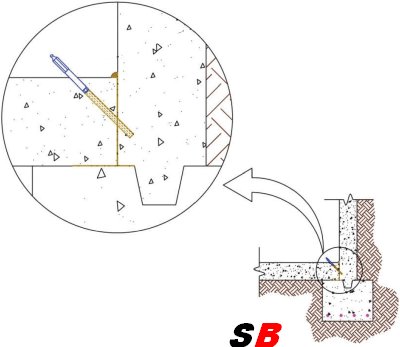
The point where water becomes visible may be easier for the water to exit than the point where it entered. A wet floor-to-wall joint may be receiving water from an adjacent wall crack. Moisture surrounding a pipe may be traveling through the annular space, along the outside of a sleeve, through cracked concrete, or beside another embedded component. Several apparently separate leaks may also be connected to one broader water source.
ASTM D8109-25, Standard Guide for Waterproofing Repair of Concrete by Chemical Grout Crack Injection, explains that injection obstructs infiltration at a particular location but does not eliminate the source of the water. The guide also recognizes that water may be diverted and later appear elsewhere. This is why assessment and follow-up belong to the repair process rather than being treated as administrative extras.
A responsible assessment distinguishes among:
- Direct observations: what can be seen, measured, photographed, or traced.
- Reasonable inferences: what the construction and leak pattern suggest.
- Unconfirmed conditions: what still requires records, testing, exploratory work, or professional judgment.
Classification should not harden into false certainty. “Water is visible along 8 ft of the floor-to-wall interface” is a defensible observation. “All water is entering through that joint” is a broader conclusion that may require additional support.
Visible leakage is the starting point
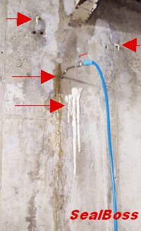
The visible discharge point should be documented in the context of the surrounding construction, drainage, joints, cavities, and previous repairs.
Establish a measurable baseline before the condition changes
The repair area should be documented before drilling, cleaning, patching, removing finishes, or installing packers or ports.
Photographs should establish the location and extent of the observed condition. A simple elevation, plan, marked photograph, or field sketch can show cracks, joints, penetrations, staining, efflorescence, corrosion marks, previous repairs, and active discharge points. The record should identify whether the area is dry, damp, intermittently wet, steadily leaking, or carrying a more substantial flow at the time of observation.
Descriptive terms become more useful when paired with a measurement. Depending on the site and responsible project requirements, the record may include:
- Drops per minute at a discrete leak.
- Timed catch volume, such as milliliters or gallons collected over a stated period.
- Wetted length or area, measured in feet or square feet.
- Estimated water head or a measured water level where that information is available.
- The rainfall, tank level, operating cycle, groundwater condition, or other event associated with the leak.
The goal is not false precision. It is repeatability. A later inspection is more meaningful when it can compare the same location under a similar condition.
Use investigation tools according to the question being asked
No single instrument reveals the complete water path. Investigation tools should be selected for a specific purpose and interpreted within their limitations.
A crack comparator card can help record visible crack width at the surface. Crack monitors or tell-tales observed over a temperature or operating cycle can help document movement, but they do not establish structural adequacy. Moisture meters can support comparative readings when the substrate and instrument are understood; they should not be treated as direct maps of concealed water movement. Thermal imaging can help identify temperature patterns associated with moisture, voids, or air movement, but the image requires interpretation and suitable environmental conditions.
A borescope may provide a view into a hollow core, cavity, drilled opening, or concealed space. Dye testing and controlled flood testing may help establish communication between locations when the structure, finishes, drainage, environmental conditions, and project authority permit them. Piezometers can record water levels or pressure conditions in soil or behind a structure when a project requires subsurface monitoring.
The tool should follow the question. The resulting observation should be recorded without claiming more than the method can establish.
Go deeper: Review Types of Concrete Cracks and Leak Sealing Methods before assigning a visible condition to an injection category.
Examine the structure beyond the wet surface
The immediate repair area should be reviewed in the context of the surrounding construction.
Relevant questions include whether positive-side access is available, whether exterior drainage is functioning, whether an original membrane or waterstop is present, whether the element is cast-in-place concrete, shotcrete, precast construction, masonry, or a combination, and whether utilities or sensitive spaces are located behind the treatment area.
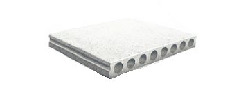
The structure’s geometry can influence water movement. Hollow-core slabs, cavities, beam pockets, construction joints, and embedded sleeves may allow water to travel farther than expected. A wet point on the interior surface may therefore be only one location within a larger network.
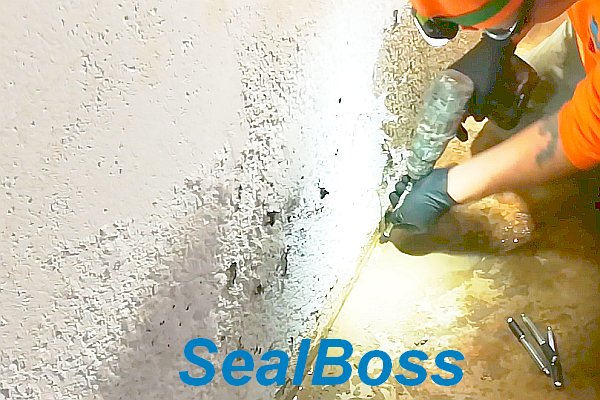
SealBoss field context — water held within concealed cells: In the Hollow-Core Concrete Slab Water Leak Repair case study, interior dripping was considered together with exterior drainage and water held within concealed slab cells. A borescope was used to examine the suspected area. The project illustrates why the visible discharge point should be treated as the beginning of the assessment, not the complete diagnosis.
The lesson is not that every hollow-core leak requires the same method. It is that the investigation should extend beyond the point where water happens to emerge.
Field context: hollow-core slab investigation
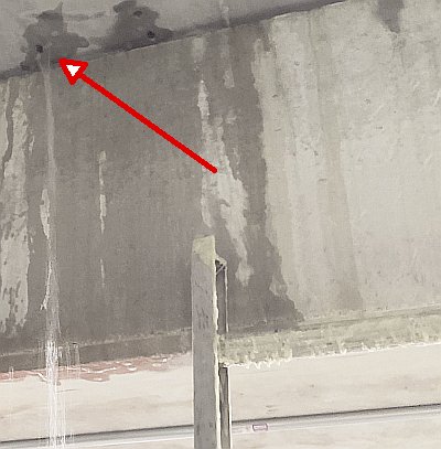
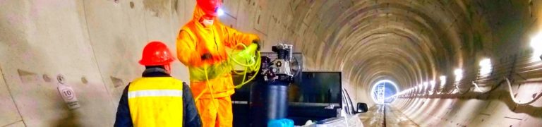
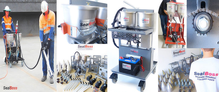
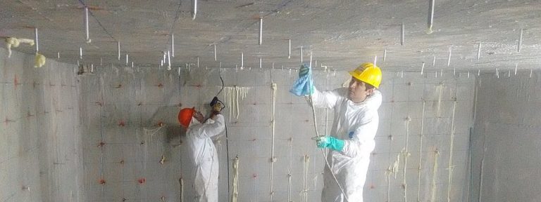
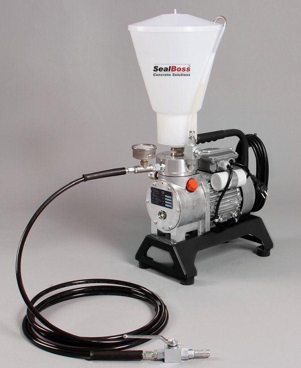
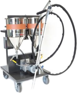
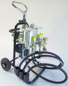
The project illustrates why leak assessment may involve exterior conditions, concealed cavities, inspection tools, injection equipment, and later monitoring rather than the wet surface alone.
Review previous repairs as part of the current condition
Earlier work can reveal useful information about the history of the leak.
Surface patches, coatings, sealants, abandoned drill holes, cut-off ports, previous injection points, repaired joints, and localized demolition may show where water was previously observed and which methods were attempted. They may also have changed the present pathway.
A patch may conceal a crack while water appears nearby. A completed injection may reduce flow at one location and make another connected opening more visible. Repeated repairs along the same joint may indicate a larger treatment area, continuing movement, limited access, or incomplete understanding of the water source.
Previous work should not automatically be described as unsuccessful. It should be documented neutrally. Where available, collect the earlier contractor’s report, product identification, photographs, repair dates, drawings, and follow-up observations.
Determine whether movement or structural distress requires separate evaluation
A leaking crack should not automatically be treated as a waterproofing problem alone.
Displacement across the crack, continuing movement, unusual width, recurring cracking beside earlier repairs, significant spalling, corrosion staining, exposed reinforcement, loss of section, changes in alignment, or other signs of deterioration may require evaluation by a qualified design professional.
ACI PRC-224.1-07, Causes, Evaluation, and Repair of Cracks in Concrete Structures, provides industry context for evaluating crack causes and selecting repair approaches. It does not replace a project-specific structural assessment.
A practical movement record may include dated width measurements, a crack monitor, photographs with a fixed scale, and observations over temperature or operating changes. These methods document change; they do not determine structural adequacy.
ASTM D8109-25 also states that cracks in below-grade concrete walls may indicate structural distress and that the overall condition should be assessed before a nonstructural waterproofing repair is selected.
Define the repair objective in practical terms
Concrete injection can serve different purposes, and those purposes should not be conflated.
The objective may be to control active water infiltration, seal a leaking crack or joint, treat an annular space around a penetration, fill a localized void, address a damaged membrane compartment, or create a broader treatment zone behind an inaccessible surface. Structural crack repair by epoxy injection represents a separate objective and should be addressed under the appropriate engineering and technical framework.
The project record should state what the work is intended to accomplish and what lies outside its scope. “Control active water entering through the documented floor-to-wall joint within the designated treatment area” is more useful than “waterproof the basement,” which may imply responsibility for conditions beyond the observed joint.
A clear objective allows the project team to identify the relevant application guideline, material family, pump category, packer or port system, inspection method, and follow-up requirement.
Consider access and the intended destination of the material
Positive-side access allows the water-bearing face to be evaluated directly. Negative-side work begins from the opposite, accessible face.
Negative-side injection can reach a crack, joint, opening, or space through the structure, but the intended destination of the material must still be understood.
The team should consider what lies behind the concrete and where injected material is permitted to travel. Adjacent property, occupied areas, drains, utilities, process equipment, waterways, membranes, soil, cavities, and finishes may all affect containment and method selection.
Section 4.6 of ASTM D8109-25 identifies existing construction, prior waterproofing installations, access, water volume or flow rate, water chemistry, temperature, humidity, and other factors as conditions that may warrant evaluating curtain grouting as an alternative to crack injection.
That decision is project-specific. Continue to Part 2: Choosing an Injection Approach for a geometry-based comparison of cracks, joints, penetrations, and broad-area conditions.
Build an assessment record that supports the next decision
A useful pre-injection record should allow another qualified person to understand the condition without relying entirely on a verbal explanation. It should identify the structure and exact treatment area; show cracks, joints, penetrations, and leak points; describe current and reported water activity; note previous repairs; record access limitations; and state the repair objective.
Available construction details—wall thickness, joint locations, waterstops, membranes, drainage components, embedded utilities, and adjacent occupied areas—should be included when relevant. Unknown wall thickness, concealed construction, inability to reproduce the reported leak, or incomplete information about prior repairs should be stated openly.
Uncertainty is not a failure of the assessment.
Unrecorded uncertainty is the problem.
Related articles, products, equipment, and technical resources
Use the links below to move from the educational framework to the relevant SealBoss application, product, equipment, case-study, or technical page.
Water Infiltration Costs & Injection Grouting
Problem context and consequences of unmanaged infiltration.
Hollow-Core Slab Case Study
Documented assessment of visible leakage and concealed cells.
Frequently asked questions
Not necessarily. It identifies where water is visible at the time of observation. Water may have traveled through connected cracks, joints, cavities, penetrations, or interfaces before reaching that point.
Depending on the question, tools may include crack comparator cards, crack monitors, moisture meters, thermal imaging, borescopes, controlled dye or flood testing, timed flow measurements, and piezometers. Each method has limitations and should be selected and interpreted by the responsible project personnel.
Displacement, continuing movement, significant deterioration, corrosion, exposed reinforcement, alignment changes, or other signs of distress may require evaluation by a qualified design professional before the condition is treated only as a waterproofing repair.
Record the location, leak activity, wetted area, defect geometry, access, prior repairs, known construction details, repair objective, measurements, photographs, and unresolved conditions.
Use the assessment to identify the repair category before selecting a system.
Current SealBoss technical documents remain controlling. Contact a qualified SealBoss technical representative when material, equipment, or application selection requires additional review.
Technical source direction: SealBoss sources control SealBoss product and equipment facts. ASTM, ICRI, ACI, OSHA, and other primary authorities provide independent industry or regulatory context within their stated scopes. Project-specific suitability, engineering decisions, warranties, and field procedures require the current controlling documents and authorized responsible parties.