









Injection Grouting Quality Control: Documentation, Verification, and Follow-Up
A clear field record helps contractors, owners, engineers, and inspectors understand what was observed, installed, changed, and left for further review.

SealBoss Corp. • Technical blog series • Technical review required before publication
Scope boundary
This part covers the project record, verification, and follow-up. Assessment is addressed in Part 1. This article does not create acceptance criteria, warranty obligations, or project-specific inspection requirements.
On this page
- Injection work is largely concealed; the record should not be
- Establish the pre-work condition
- State the repair objective and governing documents
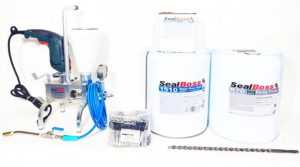
- Identify the exact material and equipment configuration
- Use a point-numbering convention that follows the structure
- Show the daily log instead of merely describing it
- Track material consumption by a meaningful unit of work
- Record deviations and unexpected conditions
- Use tiered verification appropriate to the original problem
- Describe the immediate result without promising the future
- Distinguish workmanship, product warranty, and project water-tightness obligations
- Assemble a closeout package that reconstructs the work
Injection work is largely concealed; the record should not be
Injection grouting takes place largely out of sight.
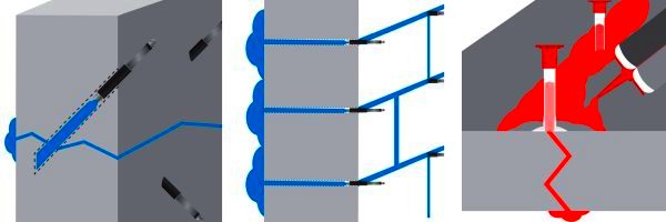
The crew can observe the concrete surface, pump, packer or port, material consumption, pressure and flow behavior, visible returns, and changes in active water. No crew member can directly see every internal crack branch, joint interface, void, cavity, or water pathway behind the structure.
That limitation makes documentation especially important.
A field record does not prove that every concealed opening has been filled. It establishes what was known before the work, which system was used, how the installation progressed, what responses were observed, where the plan changed, and what remained for follow-up.
The record should be useful to the people who performed the work and to those who were not standing beside the pump.
Establish the pre-work condition
Quality control begins before the first drill hole or surface port is installed.
The pre-work record should identify the structure, exact treatment area, relevant drawing or elevation, date, personnel, and environmental or operating conditions that may affect the observation. Photographs and marked plans should show cracks, joints, penetrations, staining, efflorescence, previous repairs, active leaks, and the boundaries of the proposed work.
“Leaking” is often too broad. The report may distinguish steady flow, intermittent discharge, dampness, seepage following rainfall, water under a known operating condition, or a reported leak that could not be reproduced during the inspection.
Where practical, photographs should be taken from repeatable viewpoints. Packer or port numbers, scales, stationing, grid references, or marked elevations can connect each image to the field record.
State the repair objective and governing documents
The report should identify what the injection is intended to accomplish. The objective may involve chemical-grout waterproofing of a defined crack, treatment of a construction joint, localized sealing of a penetration, or a designated curtain-injection area. It should not imply structural restoration unless that function is supported by engineering and product documentation.
The report should identify the documents used to plan and perform the work, including the current product data sheet, SDS, application guideline, pump manual, packer information, project specification, drawings, submittal, method statement, mockup record, inspection plan, and authorized field direction.
Revision dates matter. A document title without a revision or issue date may not establish which instruction the crew followed.
ASTM D8109-25, Standard Guide for Waterproofing Repair of Concrete by Chemical Grout Crack Injection, is intended to assist owners, representatives, architects, engineers, contractors, and authorized inspectors during selection, specification, installation, and inspection. Its multi-party scope supports a record that makes roles, decisions, and observations clear.
Section 4.7 also directs readers to related ASTM practices for chemical-grouting procedures in sewer and manhole work: ASTM F2304, ASTM F2414, and ASTM F2454. Those practices address different applications and should not be treated as SealBoss product instructions.
Identify the exact material and equipment configuration
The material record should be more specific than “polyurethane grout,” “acrylate,” or “epoxy.”
It should identify the exact SealBoss product and variation. Batch or lot information should be recorded when required by the project or current technical documents. Where the system includes an accelerator, catalyst, separate component, static mixer, or another controlled configuration, the record should identify it in the manner required by the controlling source.
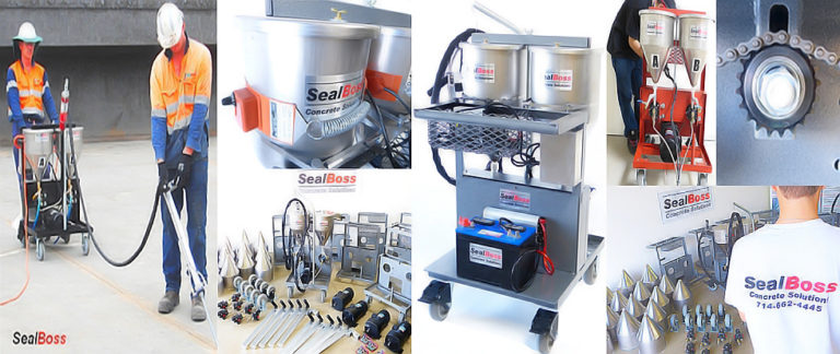
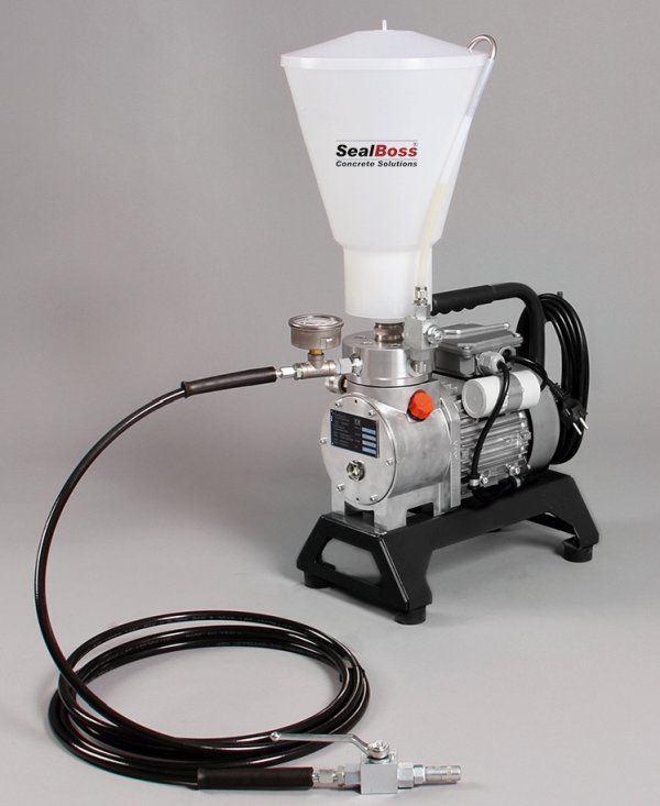
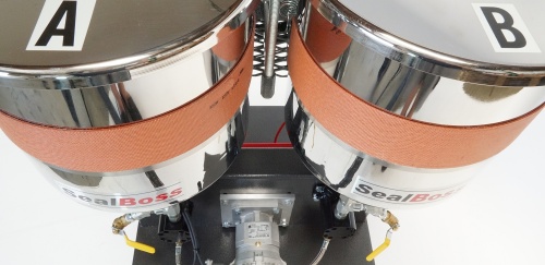
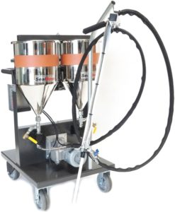
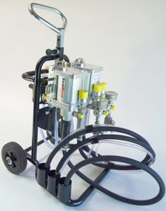
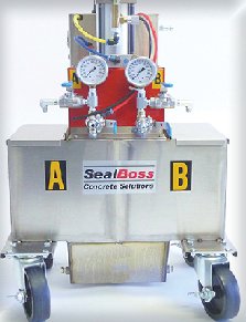
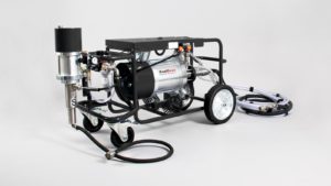
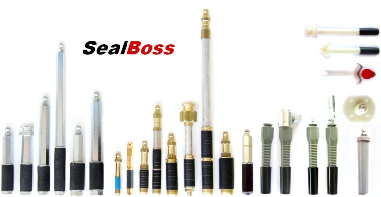
The equipment record should identify the pump model, relevant configuration, hose and valve arrangement, coupler type, and packer or port system. The applicable pump manual and application guideline should be referenced.
Substitutions should be recorded when they occur. A different pump, product variation, packer, coupler, hose, cleaner, component, or applicator may affect the original system review. Compatibility should be confirmed rather than assumed.
Use a point-numbering convention that follows the structure
Numbered injection points connect the treatment area to the daily report.
A practical convention can combine the area, structural element, and sequence number. For example:
B1-W3-P07 = Basement 1, Wall 3, Injection Point 07.
The convention is only an example. The project team should choose a system that matches the drawings, elevations, zones, and reporting requirements.
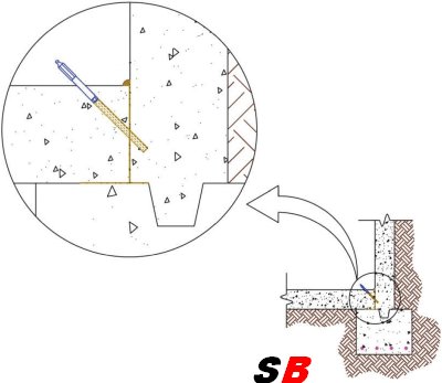
For crack or joint injection, the map may show the planned and actual sequence. For a curtain-injection area, it may record the grid, stages, zones, perimeter, or other approved layout. For a penetration, it may distinguish points around the circumference or in the adjacent concrete.
The record should identify points that were relocated, blocked, abandoned, damaged, not injected, or added during the work.
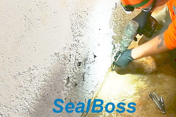
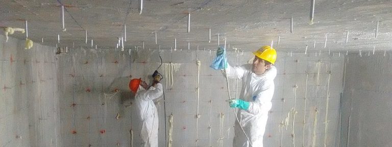
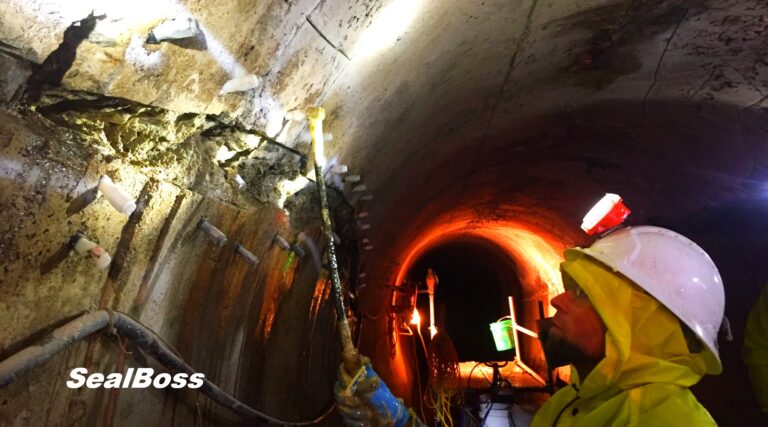
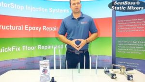
Field observation at the injection point
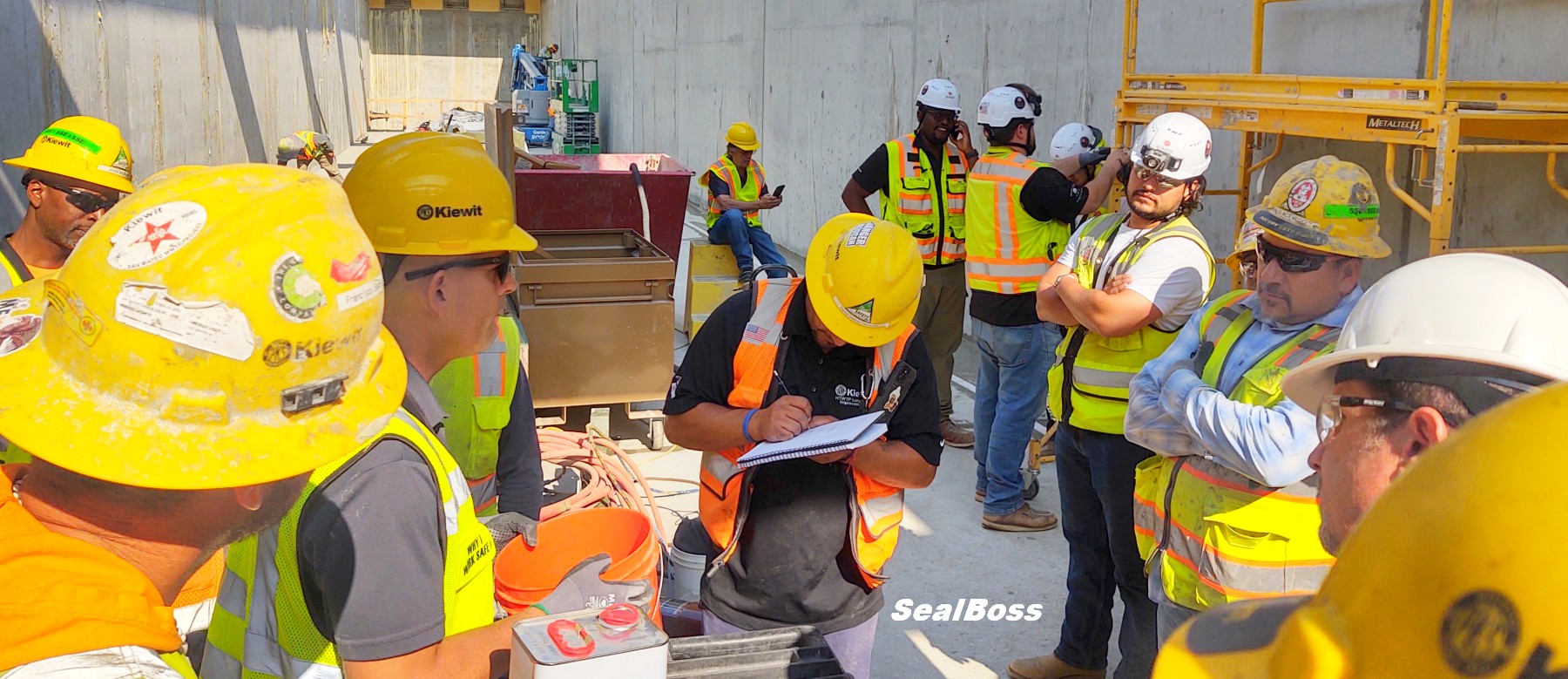
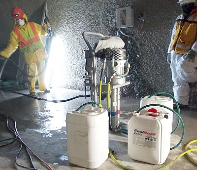
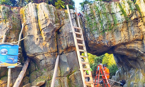
The article features a SealBoss field training session where construction professionals review crack-injection and leak-sealing procedures, equipment, and best practices at an active jobsite.
Show the daily log instead of merely describing it
A field log should preserve observations without overstating what they prove. The exact fields may vary, but the following structure provides a practical starting point.
| Point or stage | Start | Stop | Product / batch | Volume | Observed pressure | Returns / communication | Water response | Notes / deviation |
|---|---|---|---|---|---|---|---|---|
| B1-W3-P07 | 09:12 | 09:19 | [Exact product / lot] |
[unit] |
[unit] |
Material observed at P08 | Flow reduced at P07 | Continued under approved sequence |
| B1-W3-P08 | 09:24 | 09:31 | [Exact product / lot] |
[unit] |
[unit] |
Surface return at joint | No visible change | Paused; containment adjusted |
| B1-W3-P09 | 09:42 | 09:48 | [Exact product / lot] |
[unit] |
[unit] |
None observed | Area damp, no active drip | Marked for follow-up |
The sample entries illustrate format only. They are not performance criteria or field instructions.
“Material became visible at P08 while P07 was being injected” is an observation.
“The entire crack was completely filled” is a broader conclusion that may not be established by that return alone.
A decrease in water flow may show that the injection affected the active pathway. Increased resistance may reflect material reaction, restricted geometry, blockage, packer condition, or another factor. The field record should preserve the observable event first; interpretation belongs under the current guideline and the authority assigned by the project.
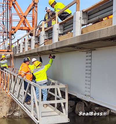
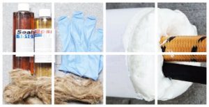
Verification under relevant service conditions

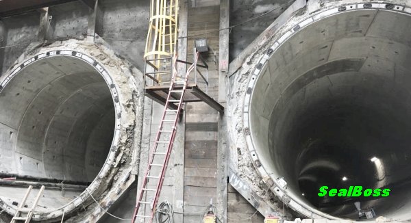
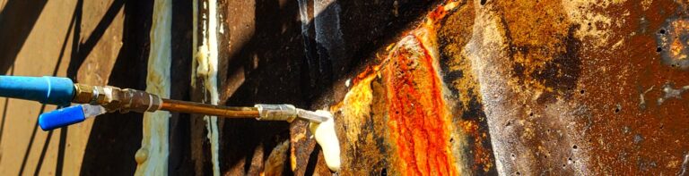
The sample daily injection log remains in the article as an editable table. This field image supports the follow-up discussion and links to a related SealBoss application example.
Track material consumption by a meaningful unit of work
Material consumption can support production tracking, scope review, and troubleshooting when it is tied to the treatment area.
A small crack project may record total use and the points treated. A larger program may track material by crack, joint, elevation, zone, grid area, stage, shift, or product batch.
Unexpectedly high or low consumption should be noted. Higher consumption may be associated with larger voids, travel beyond the anticipated area, uncontrolled discharge, or a broader treatment volume. Lower consumption may reflect restricted access, early resistance, smaller void volume, equipment interruption, or an incorrect assumption about the pathway.
Consumption alone does not establish repair quality. It becomes useful when evaluated with the point map, water observations, equipment record, material configuration, site conditions, and later inspection.
Record deviations and unexpected conditions
Injection work may reveal conditions that were not visible during the initial assessment.
A drill hole may fail to intersect the expected opening. Concrete may contain voids or embedded material. A packer may communicate with an unexpected joint. Material may emerge at a distant location. A previous repair may redirect flow. A formerly dry opening may begin discharging as the original pathway is restricted.
The deviation record should identify the location, observation, immediate action, person consulted, and any authorized change in scope or method. Where technical or engineering confirmation is required, the report should show that the relevant work was paused, limited, or redirected pending instruction.
A field adjustment should not disappear from the final report simply because the crew completed the work.
Use tiered verification appropriate to the original problem
Verification should become more structured as the consequence, uncertainty, and water condition increase.
| Verification level | Example method | What it can support | Important limitation |
|---|---|---|---|
| 1. Visual observation | Defined photographic intervals and repeatable viewpoints | Documents visible change at the treated surface | Does not quantify concealed flow or prove all pathways are addressed |
| 2. Timed flow measurement | Drops per minute or timed catch volume | Compares discharge at the same point and condition | Requires repeatable collection and comparable water load |
| 3. Moisture-pattern comparison | Moisture meter or thermal imaging | Supports comparative mapping of damp areas | Instrument and environmental limitations require interpretation |
| 4. Water-level or pressure monitoring | Piezometer, standpipe, or other approved instrument | Tracks groundwater or behind-wall conditions | Requires installation, baseline, and responsible technical interpretation |
| 5. Controlled water test | Flood, dye, or compartment test where authorized | Tests communication or water-tightness under a defined condition | May be unsuitable for occupied, sensitive, or uncontrolled structures |
| 6. Service-condition verification | Rain event, tank fill, operating cycle, or normal system load | Evaluates the repair under the condition that produced the original leak | Timing and water load may be difficult to reproduce exactly |
The project team should establish the verification method, interval, acceptance basis, and responsible party before the work begins.
Describe the immediate result without promising the future
At the end of the injection sequence, the report can state whether active water stopped, decreased, moved, remained unchanged, or could not be evaluated under the conditions present. It may identify damp areas, open packer holes, surface finishing, material curing, remaining leaks, and locations requiring later observation.
“Area dry at the completion of the shift” is a time-specific observation.
“Leak permanently eliminated” is an unsupported future promise.
ASTM D8109-25 describes chemical-grout waterproofing as potentially iterative. The water source remains, flow can be diverted, and periodic monitoring or additional repair may be required depending on the conditions.
Distinguish workmanship, product warranty, and project water-tightness obligations
Owners frequently ask whether an injection repair is “warranted.” That question should be separated into the actual obligations created by the product terms, contractor agreement, specification, and project contract.
- A manufacturer’s product warranty or disclaimer addresses the product under the exact authorized wording. Review the current SealBoss Limited Warranty / Disclaimer; do not paraphrase it into a broader promise.
- A contractor workmanship warranty, when offered, is created by the contractor’s written agreement and should identify its scope, term, exclusions, and remedy.
- A project water-tightness or performance obligation, when required, belongs in the contract documents and acceptance criteria established by authorized parties.
This article does not create a warranty or promise a water-tight outcome. Warranty language must be reviewed and approved by the authorized parties for the specific project.
Assemble a closeout package that reconstructs the work
A useful closeout package should allow the project team to understand what was done without relying on memory. It should contain the pre-work assessment, repair objective, governing documents, material and equipment identification, point map, daily logs, consumption records, deviations, photographs, immediate post-work condition, unfinished items, verification results, and follow-up requirements.
Larger projects may also require submittals, certificates, mockup records, inspection reports, training records, disposal documentation, test results, and owner-specific forms.
The closeout package does not replace the data sheet, SDS, application guideline, pump manual, specification, or professional judgment. It shows how those sources were connected to the actual work.
Use the SealBoss Injection Job Checklist, Field Reference Sheets, and Resource Page as navigation aids alongside the comprehensive technical documents.
Related articles, products, equipment, and technical resources
Use the links below to move from the educational framework to the relevant SealBoss application, product, equipment, case-study, or technical page.
SealBoss Resource Page
Data sheets, SDS documents, guidelines, manuals, and case studies.
SealBoss Limited Warranty / Disclaimer
Current authorized warranty and disclaimer wording.
Frequently asked questions
At minimum, identify the point or stage, time, exact product and batch where required, material volume, observed pressure, visible returns, water response, notes, and deviations. Project documents may require additional fields.
No. It can demonstrate communication between observed points, but it does not reveal every internal branch, void, or connected pathway.
The interval depends on the original water condition, structure, service environment, project requirements, and ability to reproduce the water load. Inspection timing and acceptance criteria should be established by the responsible project parties.
Not automatically. Product terms, contractor workmanship obligations, and project water-tightness requirements are separate matters governed by their current written documents.
Use the completed record to support closeout, follow-up, and informed future work.
Current SealBoss technical documents remain controlling. Contact a qualified SealBoss technical representative when material, equipment, or application selection requires additional review.
Technical source direction: SealBoss sources control SealBoss product and equipment facts. ASTM, ICRI, ACI, OSHA, and other primary authorities provide independent industry or regulatory context within their stated scopes. Project-specific suitability, engineering decisions, warranties, and field procedures require the current controlling documents and authorized responsible parties.