Search

news | blog

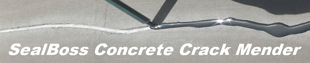
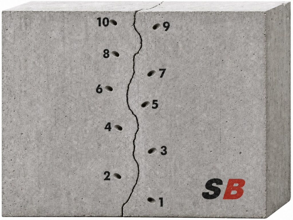
10 Minute Concrete Floor Crack Mender & Spall Repair

Ultra Fast Concrete Crack Mender and Spall Repair Resin

Discover the cutting-edge advancements in concrete repair technology. Presenting our lightning-speed, durable, and efficient crack mender and spall repair resin.

Whether you’re restoring worn warehouse floors, repairing busy parking structures, or tackling demanding concrete repairs, get the job done with exceptional speed, strength, and long-term durability.

And it doesn’t stop at concrete. This versatile, high-performance resin is also ideal for fast, durable asphalt road repairs.

Need a safe, slip-resistant surface? Simply broadcast our recommended sand aggregate for added traction and a professional finish.

Concrete Confidence: Fast Repairs. Lasting Performance.

SealBoss 6060 QuickFix

This Structural Polyurethane is an advanced material that addresses the challenges faced in repairing damaged concrete. Its unique characteristics and properties make it an ideal solution for various applications and environments.

The material’s low surface tension and viscosity allow for easy and complete saturation bonding of cracks, requiring only minimal preparation to remove loose debris.

When the material is allowed to gravity-flow to the full depth of the crack, the repair is considered structural.

Manufactured sand or quartz can be introduced into the repair process and added at a ratio of up to two parts sand to one part mixed polyurethane during crack filling to extend the material’s coverage and enhance its strength. SealBoss 6060 is highly versatile and can be applied over a wide range of substrate temperatures, making it suitable for use in frozen and cold storage warehouse applications or cold weather applications. After the repair is completed, the surface is can be ready to accept traffic in as little as ten minutes at 72°F (22°C), ensuring minimal disruption.

SealBoss 6060 QuickFix is Your Fast Concrete Floor and Road Repair System

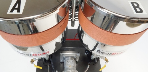
SealBoss 6060  is a super low viscosity, fast setting two component polyurethane concrete crack mender offering outstanding penetration properties, superior strength and durability.

At a mixing ratio of 1 to 1 by volume, the mixed product can be used neat or mixed with a sand aggregate to create a quick repair mortar. The product is cured chemically and does not need any moisture to react.

10 Minute Concrete Floor Crack Mender & Spall Repair


  • Very Fast Cure
  • Short Turnaround Time
  • Very Low Viscosity
  • Creates Repair Mortar with Dried / Silica Sand
  • Super Strong Polyurethane Formula
  • Outstanding Bond Strength & Penetration Properties
  • Use In Combination With SealBoss 6500 Polyurea Joint Fillers
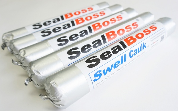
  • Products is available in Cartridges
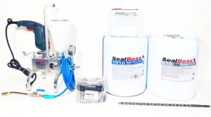
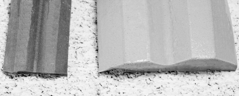
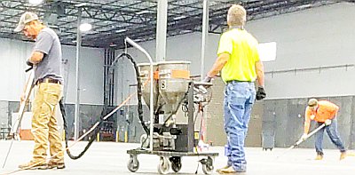
6060 QuickFix Resin is a very thin chemical cure product. 6060 polyurethane crack mender resin reacts within minutes of application. You can use it as low viscosity self leveling resin or as a quick set repair mortar. The product has excellent bond strength, compressive & tensile strength, all of which are achieved within minutes of cure. SealBoss 6060 QuickFix and fast cure SealBoss 6500 Polyurea Joint Fill products are the recommended choice for timely floor repairs in commercial warehouses and other areas of traffic. Products are also available in cartridges
Chris Coderre
National Sales Manager

In Conclusion

The ability of SealBoss 6060 to penetrate deeply into cracks and bond directly to the concrete-aggregate matrix ensures long-lasting and reliable repair.

Structural Polyurethane is adaptable for use in extreme temperature conditions, making it suitable for a range of industries and applications where traditional repair materials might fail.

The rapid curing time of SB 6060 minimizes downtime and disruptions, allowing for swift resumption of normal activities in the repaired area.

Given the material’s versatile nature, it can be used to address a wide variety of concrete damage, including cracks, spalls, and other structural defects.

The compatibility of SealBoss 6060 with Portland Cement Concrete (PCC) enables a smooth blending with pre-existing concrete structures, minimizing the aesthetic effects of repairs.

By incorporating SealBoss 6060 Structural Polyurethane into the repair process, professionals can effectively extend the service life of concrete structures while maintaining their appearance and structural integrity. This innovative material offers a highly effective, efficient, and durable solution for restoring distressed concrete and ensuring its longevity.

10 Minute Concrete Floor Crack Mender & Spall Repair Related Articles


Learn More

Feel free to reach out to us at 714-662-4445 for any inquiries, or submit a contact request here. We are eager to assist you in finding the right solution. Expert technical representatives are available to provide on-site support upon request.

Contact Your SealBoss ® Technician

Hollow Core Concrete Slab Water Leak Repair

Hollow Core Concrete Slab Water Leak Repair

What is a Hollow Core Slab ?

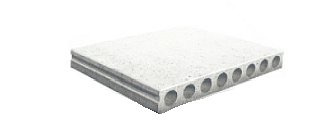
Hollow core slabs are precast, prestressed concrete members commonly used to construct floors and roofs in multi-story buildings, parking structures and other commercial construction.

As the name suggests, longitudinal hollow cells run through the interior of the slab. These voids reduce the amount of concrete required and the weight of the structural member while maintaining an efficient structural cross section.

For waterproofing contractors, however, those same hollow cells create a unique challenge.

If water enters an unsealed end, joint, penetration or other opening, it may collect inside a cell and travel through the slab before finding an exit. As a result, the location where water appears is not necessarily the location where water entered the structure.

This makes proper investigation especially important when repairing hollow core slab leaks.

Hollow Core Concrete Slab Water Leak Repair

Diagnosing and Sealing Water Intrusion in a Parking Garage with SealBoss 1510 Water Stop Foam

A water leak in a hollow core concrete slab is not always as straightforward as it appears.

Water dripping from a crack in the ceiling may have entered the structure several feet away. Once water reaches the hollow cells inside a precast slab, those concealed channels can collect water and allow it to move beyond the original point of entry.

That was the challenge on this parking garage repair project.

The visible symptoms were leaking cracks, water dripping onto parked vehicles, staining and efflorescence. But simply injecting the locations where water appeared would not necessarily solve the complete problem.

The contractor first had to determine where the water was entering, where it was traveling, and how it was escaping from the hollow core slab system.

The Problem: Water Dripping Into the Parking Garage

The building owner was experiencing water intrusion through hollow core concrete slabs and along exterior wall and sill plate cold joints above a parking garage. Water was dripping onto vehicles below and leaving visible watermarks, efflorescence and rust staining on portions of the concrete and walls. A waterproofing contractor was brought in with two objectives:

  1. Stop the active leakage through the cracks and joints.
  2. Determine the source of the water entering the hollow core slab system.

The second objective proved to be just as important as the first.

Finding the Source of the Water

Before beginning injection work, the contractor and SealBoss Regional Sales Manager inspected the exterior of the building. A significant drainage condition quickly became apparent. Downspouts were discharging stormwater directly onto grassy areas adjacent to the building. The surrounding grade provided little slope to move the water away from the structure, allowing runoff to collect near the exterior wall.

This provided an important clue.

Rather than treating the ceiling leaks as isolated cracks, the repair team investigated whether exterior water was entering through the building perimeter and reaching the hollow core slab cells. The evidence soon confirmed it.

The Hollow Core Was Holding Water

When drilling began for installation of the injection packers, water poured from the slab. The hollow core cell was not simply damp—it had accumulated a substantial amount of water. Before injection could proceed, the trapped water was allowed to drain.

But the investigation did not stop there.

Because water can migrate through openings and interconnected areas within a hollow core assembly, weep holes were drilled into adjacent cells to determine whether the problem extended beyond the first affected core. Water was discovered in another cell as well. That cell also had to be drained.

This was an important part of the diagnosis: The visible ceiling leak represented only one portion of a larger concealed water-intrusion path.

A Borescope Revealed the Entry Point

To investigate farther inside the slab, the contractor used a borescope. The inspection confirmed water intrusion near the location where the hollow core had been closed with a plastic end cap. The combination of exterior drainage observations, water discovered inside the slab cells and the borescope inspection provided a much clearer picture of the leak mechanism.

Water was reaching the building perimeter, entering the hollow core system and accumulating inside the cells before eventually escaping through cracks and joints into the parking garage below. With the leak path identified, the repair could address both the visible leakage and the likely entry locations.

A Two-Part Injection Strategy

The contractor adopted a two-part repair strategy.

Step 1: Seal the Leaking Cracks

The first objective was to stop water escaping through cracks in the hollow core slab and dripping onto vehicles. After the affected cores were drained, the leaking cracks were pressure injected using SealBoss 1510 Water Stop Foam.

SealBoss 1510 is a hydrophobic, water-activated polyurethane injection grout designed for leak sealing and water cut-off applications. When the resin encounters moisture, it reacts and expands to form a polyurethane foam within the crack, joint or void.

Its low viscosity helps the resin penetrate tight pathways before reaction, while the SealBoss 15X Accelerator allows the reaction characteristics to be adjusted for the application.

Step 2: Address the Water Entry Path

Stopping the water where it emerged from the slab was only one part of the repair. The exterior cold joint and the affected hollow core cell ends also had to be addressed to reduce continued water intrusion into the slab system. SealBoss 1510 NSF/ANSI 61 Water Stop Foam was therefore injected along the exterior cold joint in areas showing signs of water movement, including efflorescence and rust staining. The affected hollow core cells were also injected approximately 6 inches from the end caps to create a leak-sealing barrier at the suspected entry areas. This approach attacked the problem from both directions:

Seal the pathways where water was escaping and seal the locations where water was entering the hollow core system.

Crack and Joint Injection Using the SealBoss 1-2-3 at 45 Degree Method

The visible leaking areas were injected using the SealBoss 1-2-3 at 45 Degree injection method.

For this project, mechanical injection packers were installed approximately 12 inches from the joint. Approximately 1/2-inch holes were drilled at a 45-degree angle toward the joint so that the drill path would intersect the intended injection area within the concrete. Angled drilling is commonly used in concrete crack injection because it allows the injection point to intersect the crack or joint below the surface rather than relying on drilling directly into the visible opening.

The SealBoss 1-2-3 at 45 Degree method emphasizes:

  • planning and mapping the injection locations,
  • properly drilling and installing the injection packers,
  • injecting the targeted crack or joint thoroughly,
  • and reinjecting as required until adequate material penetration or product refusal is achieved.

Actual packer spacing, drilling geometry and injection procedure must always be adjusted to the conditions of the structure, crack configuration, concrete thickness, water flow and injection material.

On this project, SealBoss 1510 was injected until the targeted joint had accepted sufficient material and the injection response indicated the water-bearing pathway had been filled.

Why SealBoss 1510 Was Used

SealBoss 1510 Water Stop Foam is designed specifically for water cut-off and leak-sealing injection applications.

For this type of repair, several characteristics were particularly useful:

  • Hydrophobic, water-activated polyurethane chemistry
  • Low viscosity for penetration into cracks and water-bearing pathways
  • Adjustable reaction time using SealBoss 15X Accelerator
  • Approximately 30–40 times expansion depending on accelerator concentration and application conditions
  • Semi-flexible reacted foam
  • 100% solids and solvent-free formulation
  • NSF/ANSI 61 drinking-water-contact certification
  • Compatibility with the SealBoss pump, packer and injection equipment system

The material reacts with moisture within the structure, making it well suited to injection into leaking cracks, construction joints and concealed water-bearing voids.

Verification After Injection

The weep holes in the hollow core cells were intentionally left open following the repair.

This provided a simple way to observe whether additional water continued to enter and accumulate in the cells after injection.

Leaving a means of verification was important because successful leak repair involves more than seeing an active drip stop during injection. The repair should also be observed afterward to determine whether the original water pathway has been interrupted.

The building owner was also advised to monitor the affected areas during future wet weather and seasonal thaw conditions.

Correcting the Drainage Condition

Injection addressed the water intrusion through the concrete structure, but the exterior drainage condition also needed attention.

The owner was advised to install drainage boxes or make other appropriate drainage improvements in areas where stormwater collected near the building.

This is an important lesson in leak-sealing work:

Injection can seal a water pathway, but managing the water source can be equally important.

When downspouts, grading or surface drainage continuously direct water toward a structure, correcting those conditions can reduce hydrostatic exposure and help prevent water from finding another route into the building.

A successful waterproofing strategy should therefore consider both the concrete defect and the conditions delivering water to it.

Key Lessons From This Hollow Core Slab Repair

This project demonstrates why hollow core slab leak repair often requires more investigation than simply locating a wet crack.

  • Follow the Water
    The point where water exits the concrete may not be the point where it enters.
  • Investigate the Hollow Cells
    Water can accumulate inside hollow core cells without being visible from the exterior.
  • Check Adjacent Cells
    Finding water in one cell does not automatically mean neighboring cells are dry.
  • Use Inspection Tools When Necessary
    A borescope can provide valuable information about conditions that cannot be seen from the slab surface.
  • Drain Before Sealing When Required
    Removing accumulated water made it possible to better evaluate the affected cells and proceed with the repair.
  • Treat the Entry and Exit Paths
    Sealing only the dripping crack may leave the original water-entry pathway untreated.
  • Look Beyond the Concrete
    Drainage, downspouts, grading and other site conditions can contribute directly to recurring water intrusion.

A System Approach to Hollow Core Slab Leak Repair


The contractor:

  • identified the exterior drainage condition,
    located water trapped inside the hollow core cells,
    drained the affected cells,
    checked adjacent cells,
    used a borescope to investigate the suspected entry area,
    injected the leaking cracks and cold joint,
    sealed the affected hollow core ends,
    and left weep holes available for post-repair observation.

The success of this repair came from treating the leak as a water-management problem rather than simply a visible crack.

Using the SealBoss 1510 Water Stop Foam System together with mechanical injection packers and the SealBoss P2002 injection pump provided the contractor with a complete pressure-injection approach for the water-bearing cracks, joints and hollow core areas encountered on the project.

Important Note on Prestressed Hollow Core Slabs

Hollow core slabs are prestressed structural members. Drilling and repair work should be performed by qualified personnel with an understanding of the slab configuration and prestressing system. Injection hole locations and drilling procedures must be appropriate for the specific structure; the dimensions described in this case study represent this particular project and should not be treated as a universal drilling specification.

Need Help With a Hollow Core Slab Leak?

Water inside hollow core concrete can be difficult to diagnose because the visible leak may tell only part of the story.

SealBoss provides professional polyurethane injection resins, pumps, injection packers, accessories and technical support for concrete leak-sealing and water-stop applications.

For assistance selecting an injection system or evaluating a hollow core slab water-intrusion application, contact a SealBoss technical representative.

Products Used:

Injection Resin: SealBoss 1510 Hydrophobic Water Stop / Leak-Seal Foam w/ 15x Accelerator

Injection Packers: SealBoss 1/2” 13-100 Evolution Aluminum Packers

High Pressure Pump: SealBoss P2002 Single Component Injection Pump

Cleaning Materials: R70 Pump Flush, Xylene, rags, bucket

Additional Tools: 18” x 1/2″ drill bit — 3/8” Crescent Wrench — Dead Blow Hammer
Hammer Drill — Access 110v Power — Vacuum

SealBoss ® 1510 NSF Hollow Core Slab Water Stop Foam:

  • Hollow Core Slab Leak-Seal Repair, Crack & Joint Leak Sealer

SealBoss ® 1510 Hollow Core Concrete Slab Seal Foam Advantages:

  • Low Viscosity
  • Fast Cure Time
  • Advanced and Proven SealBoss ® Product-Pump-Packer System


Bestselling SealBoss ® Brand P2002 Injection Pump Advantages

  • Light Weight Injection Pump
  • High Quality Components for Durability
  • Proven Design – Thousands of Units Sold
  • Easy To Clean
  • Easy To Maintain
  • Heavy Duty For Daily Use
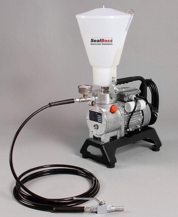
  • Pressure Gauge, Hose Set, Hopper Included
  • Recommended For Beginners & Injection Pros
  • > 5000 PSI Injection Pressure Possible

In Person and Video training is available upon request, contact SealBoss today to speak to your regional technical representative on our SealBoss full system solutions and offerings. 

 “While providing jobsite assistance, support and training, we create a positive learning environment where confidence and a level of comfort can be achieved in a short period of time allowing for successful repairs to be continued after the training.

From training new companies to new employees, SealBoss has continued to provide support to our users for 36 years.

With a knowledgeable technical support team, we are here to help with any questions you may have”

leaking-crack-repair-sealboss
Technical Sales Team
Contact Your SealBoss ® Technician

Crack Injection Guideline – 1 2 3 at 45 Degree

Crack Injection Guideline
1 - 2 - 3 at 45 Degree

SealBoss 1 2 3 at 45 Degree Injection Guideline Leak-Seal & Water Stop Crack Injection

Crack Injection Guideline
1 - 2 - 3 at 45 Degree

Injecting Trust - One Crack at a Time

A Comprehensive Injection Guideline featuring Detailed Information on Injection Packers and their Correct and Intended Use

Introduction

Cracks in concrete structures are more than just cosmetic issues—they can compromise integrity, allow water intrusion, and accelerate rebar corrosion. The SealBoss 1-2-3 at 45 Degree Crack Injection Guideline provides a proven, systematic approach to crack injection that ensures effective leak sealing and structural protection. By following three critical steps—preparing and mapping packer placement, installing the packers, and executing the injection at a 45-degree angle—contractors can achieve durable, high-quality results. This article outlines best practices, technical details, and important considerations to help professionals optimize their injection process and maximize success, one crack at a time.

The SealBoss 1-2-3 at 45 Degree Crack Injection Guideline

  • Step 1 – Preparing and Mapping Out Packer Placement
  • Step 2 – Installing the Packers
  • Step 3 – Executing the Injection Process
  • 45-Degree Angle – Recommended Packer Angle / Positioning Guideline

Optimal Techniques and Considerations

The SealBoss 1-2-3 at 45 Degree Injection Guideline highlights the three fundamental steps of the injection process while emphasizing the importance of a standard 45-degree angle for packer placement. Although the 45-degree angle is a widely accepted practice, certain situations may require deviation from this rule, as discussed in this article.

Additionally, it is advised to target each injection port three times during the injection procedure – as a general rule – to ensure adequate density and penetration of the chemical grout within the structure. Injection Packers that persistently absorb product should be injected repeatedly, as many times as needed, to ensure a lasting seal.

Injection Packer Spacing

Mechanical injection packer spacing, also referred to as port spacing, in the context of leak-seal crack injection is contingent upon several site-specific conditions, such as crack width, substrate thickness, water flow, and product properties.

In numerous instances, an 8-inch (20 cm) to 1-foot (30 cm) on-center spacing serves as a suitable initial distance. Hairline cracks necessitate tighter spacing, as the product is less capable of traveling far. Consequently, the tighter the cracks, the closer the required spacing.

Injection Packer Placement

In the majority of cases, injection packers should be arranged in a staggered manner by alternating drill holes to the left and right of the crack while drilling at a 45-degree angle toward the crack, thereby forming a stitch grouting pattern. This method enhances the likelihood of intersecting the crack during drilling and reduces the probability of concrete cracking and spalling during packer installation or the high-pressure injection process. Injection should commence from the bottom and proceed upward.

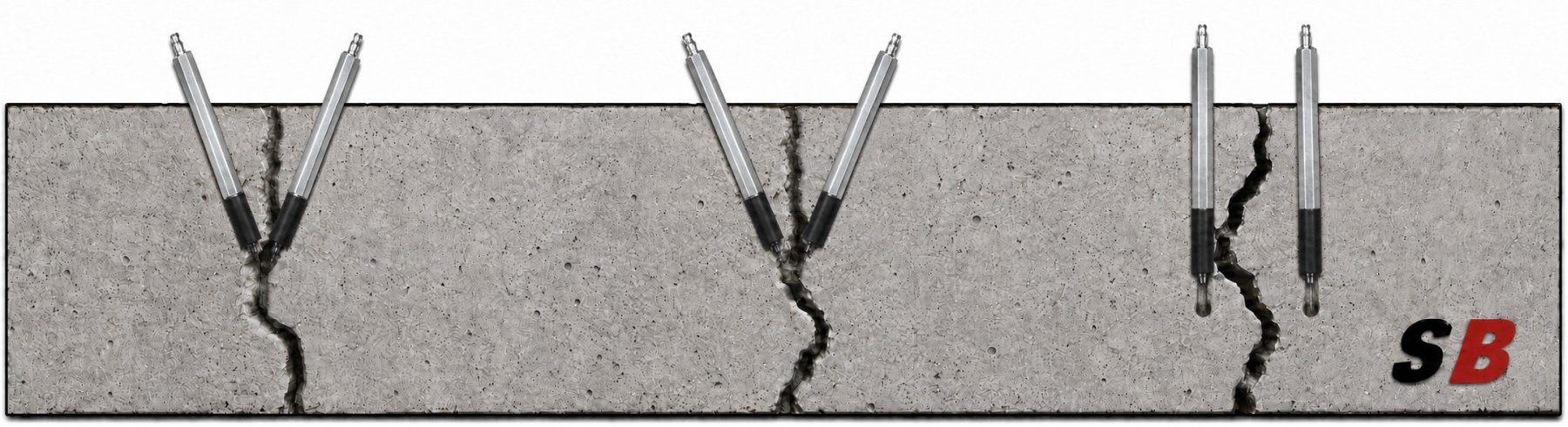
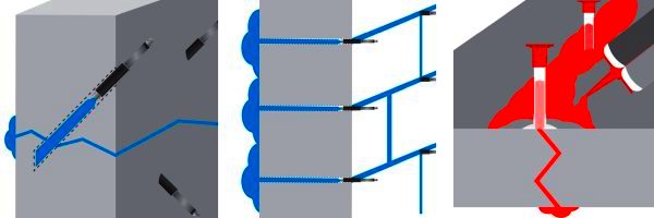
The illustration below shows how angled drilling increases the likelihood of intersecting the crack, as shown on the left and in the center. In contrast, straight drilling often misses the crack, creating a dead-end hole, as shown on the right. Packers installed in these holes do not communicate with the crack, preventing the injection resin from filling and sealing it.

Angle Drilling Injection Packers SealBoss

45 Degree Angle Drilling and Packer Placement

The optimal method for packer placement involves positioning at a 45-degree angle. For structures with a thickness exceeding 6 inches (12-15 cm), SealBoss recommends a 45-degree angle as the most effective strategy for intersecting the crack at the midpoint of the structure. This is accomplished by initiating drilling a few inches to the left or right of the crack at an angled trajectory toward the crack itself, rather than drilling directly into it. This technique enables the requisite “inside-out” product flow for optimal crack penetration.

For instance, in a 10-inch thick concrete wall, one should move approximately 4-5 inches (8-10 cm) away from the crack and drill at a 45-degree angle toward it to attain the desired target. Initiating drilling with a straight entry and subsequently angling the drill at the required angle is beneficial.

Typical drill spacing along the crack’s surface ranges between 6-12 inches (10-20 cm) depending on the crack’s thickness. Hairline cracks necessitate closer spacing than larger cracks, as the material will not travel as far. Stagger drill holes from one side of the crack to the other, intersecting the crack during drilling.

Optimizing Drill Hole Distance from the Crack 

When determining the spacing of drill holes from a crack for chemical grout injection, it is essential to understand the relationship between the hole’s distance from the crack and the depth at which it intersects the crack. Here is a detailed explanation:

  • Depth of Intersection: The greater the distance between the drill hole and the crack, the deeper is its intersection with the crack inside the structure, leading to a deeper point of injection.
  • Considerations for Thicker Structures:  In thicker structures, a deeper injection point is usually favored. Yet, it is essential to factor in the drill bit’s length and reach, as they play a crucial role in determining the optimal distance for the drill hole. Always allow for a margin of error and ad at least a margin of 2 inches to the calculated drill bit reach needed.
  • Avoiding Dead-End Drill Holes: A drill hole that misses the crack cannot facilitate the injection of the chemical grout into the structure. Such holes are termed “dead-end drill holes” and are ineffective for the purpose of grout injection.

Determining the Required Minimum Length for a Drill Bit

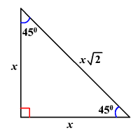
When drilling at a 45-degree angle, we encounter a specific triangle called the 45-45-90 triangle, which follows the principles of the Pythagorean theorem.

In this 45-45-90 triangle, both legs, marked “X”  are of equal length. X is the distance the drill hole is placed away from the crack. Therefore, when drilling at a 45-degree angle, if we assume the crack is perpendicular to the surface, the depth at which the drill hole intersects the crack will be the same as the distance of the drill hole from the crack. To determine the minimum drill depth, or the distance from the drill hole surface to the crack, use the formula:
Distance from crack X √2, which is approximately 1.414.

To simplify and account for variations we use the factor 1.5 to calculate the absolute minimum drill hole depth necessary to intersect the crack. 

For a 5-inch distance from the crack, the calculation would be: 5 × 1.5 = 7.5 inches. Therefore, the drill hole should be at least 7.5 inches deep to guarantee intersection with the crack for injection in near perfect conditions.

For a 6-inch distance from the crack, the calculation would be: 6 × 1.5 = 9 inches. Therefore, the drill hole should be at least 7.5 inches deep to guarantee intersection with the crack for injection in near perfect conditions.

Now add at least 2 inches of drill bit reach to the calculation. It is essential to remember that not all cracks might run perfectly perpendicular to the surface, so always consider the specific conditions of your project.  

In summary, while determining the placing of drill holes, it is important to balance the desired depth of injection with the capabilities and reach of your drilling equipment to ensure effective grout injection.Remember, the effective reach of a drill bit and its actual length differ.

Always ensure your drill bit has the necessary length to effectively intersect the crack!

General Injection Packer Preparation – Drill and Flush


Safety Gear

Consistently wear appropriate protective gear and goggles, adhering to data sheet and SDS instructions.

Cleaning

If required, clean the crack or joint’s face using a wire brush, pressure washing, or similar method. A clean surface facilitates the identification of cracks and problematic areas.

Spacing

Mechanical injection packer spacing, also known as port spacing, is contingent upon various site conditions such as crack depth and width, substrate thickness and state, water flow rate, and the product’s physical and chemical properties.

An 8-inch (20 cm) to 1-foot (30 cm) on-center spacing is suggested for the majority of situations. Hairline cracks necessitate tighter spacing compared to wider cracks. The tighter the cracks, the closer the required spacing, as the product must travel deeply enough into the structure to form a permanent seal.

Determine the spacing, pattern, and depths of the drill holes. Based on the crack’s width, space the packers at a distance of approximately 6-18 inches (10-45 cm). The tighter the cracks, the closer the required spacing. Hairline cracks result in limited water stop and leak-seal grout travel, necessitating tighter packer spacing, while wider cracks permit easier flow and broader packer spacing.

Stagger drill holes from one side of the crack to the other (left/right), thus forming a stitch grouting pattern. This technique increases the chances of intersecting the crack during drilling while decreasing the likelihood of cracking and spalling the concrete during packer installation and the high-pressure injection process.

Typically, injection should begin at the bottom and move upward, pushing the product against gravity and water flow, thereby achieving a higher density in the process.

Injection-Packer-Drilling-Pattern-45-Degree-Holes SealBoss


Exceptions to the 45 Degree Injection Rule – Straight Drilling

As with any rule, the catchy SealBoss 1-2-3 at 45-Degree Rule has its limitations and exceptions. Here are three notable examples:

  • Drilling into Joints
    Drilling into joints, such as concrete tunnel segments, is predominantly performed in a straight manner.
  • Thinner Stuctures
    Concrete structures with a thickness of less than 6 inches may not permit angle drilling, as this can result in cracking and spalling of the concrete.
  • Badly Deteriorated Substrate
    Similar issues can occur in severely deteriorated concrete substrates and in concrete of inferior quality. In such situations, it is recommended to drill and install packers directly into the crack without completely penetrating the structure.

SealBoss offers an extensive range of injection equipment and pumps to accommodate your project. Consult a SealBoss technician for detailed information and assistance. We look forward to helping you with your project.

Drill Dust

When drilling deeper holes, periodically extract your drill bit to remove drilling dust and prevent your drill from binding up.

Rebar

Most concrete structures contain rebar steel reinforcement to provide structural strength. In an ideal, crack-free structure, concrete protects the rebar from corrosion by insulating it from moisture and air while maintaining a high pH environment. However, when cracks form, this shield is compromised, allowing air, environmental gases, and water to cause carbonation, and subsequently corrosion of the rebar, which  forms rust expands to expands its original volume. The expansion of rusted rebar exerts high forces against the concrete, resulting in further deterioration, cracking, and spalling. Chemical grout injection protects rebar and can mitigate these processes.

Rebar often slows down the drilling process. When your drill bit contacts rebar, the sound changes, the quantity of drilling dust may be reduced, and the progression slows down or may even stop.

Some drill bits enable drilling through rebar, although this is generally not recommended and may even be prohibited, as it can weaken the concrete structure. In such cases, relocating the drill hole is the only option. If you repeatedly hit rebar, consider drilling straight into the crack. Dead-end drill holes, the holes that are not used for injection, must be patched and sealed before injection to prevent leakage.

Flushing / Cleaning Drill Holes Prior to Injection

Overview

Drilling debris can thicken the product during injection, resulting in higher injection pressures and reduced penetration in fine cracks. It is best practice to remove concrete dust and debris from the drill holes by flushing with a water hose until clean water is observed. You can use a water hose to flush debris from the hole.

Vacuuming out the dust can also be helpful if flushing is not possible.

Blowing out the debris is another option; however, be aware that dust can be an inhalation hazard, and appropriate gear is mandatory.

Flushing / Cleaning of holes is not necessary if water is actively running from your drill holes.

Drill Hole Water Flushing Detail

Low Pressure Flush

For low-pressure flushing, simple tools like a plastic water squeeze or spray bottle suffice. This method can remove debris from the drill hole and introduce water into the drill hole.

If available on site, a water hose can be used to flush the drill holes.

Using a Dedicated Flushing Water Pump

A dedicated water injection pump is suitable for both low-pressure drill hole flushing with a hose and on-site pressure crack flushing with water through injection packers.

While drill hole flushing serves to remove debris from the hole only, high-pressure water flushing can provide insights into material flow, expected product penetration distance, and introduce moisture to enhance product reactivity.

For such high-pressure applications, a dedicated water flushing pump is essential.

After clearing the drill hole, an injection packer is positioned. The water pump is then linked to channel water under high pressure via the injection packer into the into the crack, flushing it in the process.

If the crack remains unresponsive to taking on water, it might indicate that the hole is not linked to the crack. In such cases, a new drill hole has to be established and retested with water.

While high-pressure flushing is not typically required for most injection projects, it can offer benefits in specific scenarios.

It is imperative not to use the same pump for water injection that you use for dispensing polyurethane resin. Given that polyurethanes are activated by water, even the slightest moisture can result in pump malfunction.

Final Thoughts

Equipment limitations may render flushing infeasible; however, most injections will succeed without additional water introduction, even in seemingly dry crack environments. If the product does not immediately contact water, it will cure over time as natural moisture in the concrete stimulates curing and hardening, potentially at a slower pace.

Additional Injection Packer Installation Recommendations

Mechanical Packer Fundamentals

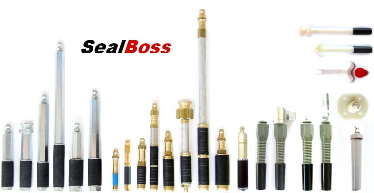
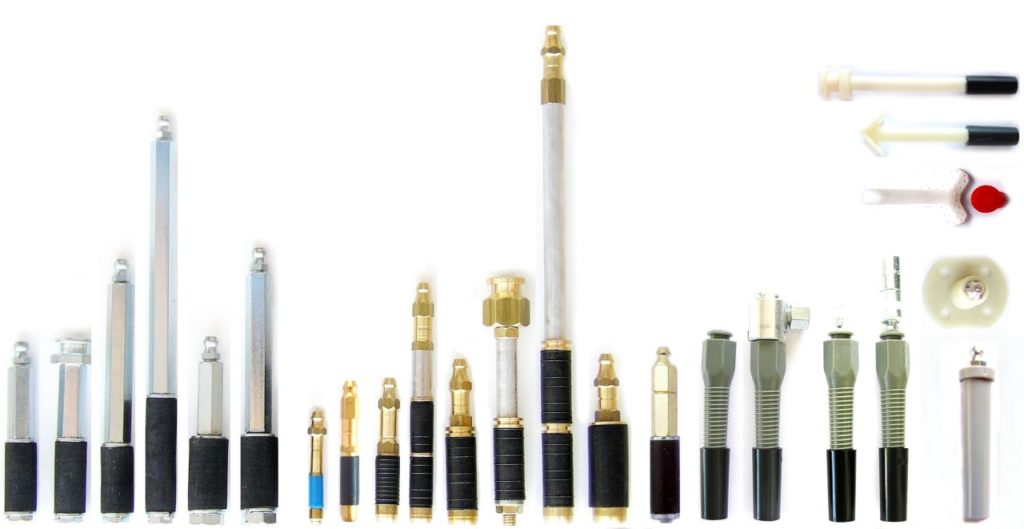
For optimal performance, packers and drill holes must possess adequate quality to endure injection pressures without leakage or displacement within the crack. Notably, even superior packers may rupture or leak under certain conditions. SealBoss Mechanical Packers, available in various sizes and designs, are recommended for pressure injection. These packers feature a threaded shaft with a rubber base; upon insertion, tightening the shaft compresses the rubber within the drill hole, generating a compression seal. Standard packer diameters range from 1/4 to 3/4 inches, with industry norms between 3/8 and 5/8 inches. In poured concrete substrates, drill holes serve as solid channels directing resin to the crack, enabling the use of shorter packers. In substrates with potential voids, such as block walls, stone, and brick, SealBoss advises employing longer packers to ensure a definite grout delivery channel to the crack being sealed.

Mechanical Packers Installation

To seal against the drill hole, mechanical packers require tightening, which expands the rubber seal. Packers may be pre-tightened by hand to seat the rubber snugly, approximately 1/4 inch (5 mm) inside the drill hole. Correct installation prevents concrete cracking around the drill hole’s exterior. Depending on packer design, using an appropriate ratchet/nut, wrench, or electric driver for tightening is highly recommended. Packers should be securely tightened to withstand injection pressures without over-tightening.

SealBoss Hammer-In Ports

SealBoss Hammer-In Ports are also frequently utilized. These ports are seated using a hammer at moderate force, with an electric driver or hand tool and a suitable socket employed to screw the zerk fitting into the port. Hammer-in ports typically do not achieve the same injection pressures as mechanical packers and should be reserved for applications where maximum injection pressures are not essential.

Packer Connectors

Packers are typically equipped with a quick-connect system, either a zerk type or button head/slide coupler type.

Zerk Type Connector

The zerk type is most prevalent. Applicators must push the coupler over the zerk fitting and maintain alignment with the packer. To disconnect, applicators “break” the connection by pushing the connector sideways.

Button Head / Slide Coupler

The button head type provides a more secure connection. The operator slides the coupler on and off the packer, ensuring a secure, tight connection that is less prone to unintended disconnection and leakage. When executed properly, the applicator does not need to hold the coupler in place, a significant advantage in overhead injection and instances requiring large product volumes through one packer.

SealBoss Packers

SealBoss offers an industry-leading array of injection packers and ports for diverse situations and requirements. Contact a SealBoss representative for packer recommendations tailored to your project.

Injection Products


Before You Start Injection

Before injection, review the product datasheet instructions. Ensure your pump is in fully operational condition and completely devoid of moisture before preparing SealBoss Water Stop and Leak Sealing Products for injection.

It is prudent to flush the pump with SealBoss R70 before using any resin/foam grout.

Injection Procedure

When products are prepared for injection, have a cup available to dispose of some resin to ensure purity. Start the pump at the lowest pressure setting. After connecting your grout injection hose to the secured and tightened packers, initiate the injection process.

Use the shut-off valve at the injection hose’s end whenever the hose is moved, remember that some pumps need to be manually stopped .

Starting from the bottom, securely connect your injection line to the packer and commence with the lowest pressure capable of moving resin into the crack. Generally, injection pressure will decrease as material flows, but pressure may need to be increased as products thicken and move into tighter cracks and fissures.

Maintain a slow injection rate as resin begins to show and flow from the crack. Pausing and restarting the process for a minute may be necessary to allow material reaction and thickening.

Monitor consumption rates and cease injection when consumption equals leakage. A typical observation involves reduced water flow from the crack’s face and/or reacting material exiting the crack’s face. This indicates successful penetration and results.

If the product does not advance along the crack, disconnect and proceed to the next port. Applicators must ensure sufficient material is injected into each crack to achieve optimal product density for a durable seal.

It is recommended to inject three to five packers while observing product flow, travel, and refusal from the crack.

Reinjecting those three to five packers—typically up to three times (1-2-3 at 45 degrees) or until product refusal—is crucial. The crack must be adequately filled with as much product as possible without excessive product loss from the crack. Sufficient material consumption and product density in the injected area must be monitored to achieve a solid and successful repair.

Injection Packers that continue to consume considerable product amounts should be injected a third time or as often as necessary to create a permanent seal.

SealBoss Oakum Soakum Technique

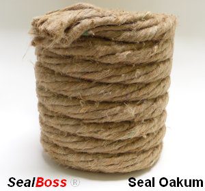
In cases where excessive resin flows out or washes out due to high water flow, resin-soaked SealBoss Oakum can be employed to form a temporary plug, allowing the product time to react, expand, and seal.

Caution: Be prepared for the possibility of product ejection from the structure or around drill holes, as well as packer blowouts. High-pressure injection equipment may cause product to travel further than anticipated, potentially appearing several feet from the injection point. Small cracks may become visible after the injection process.

Quality Injection Job

Injection often necessitates a two-person team, with one individual operating the valve and hose while another manages the pump. Create a dense seal! Inadequate material consumption alone can yield differing results in the same injection application. If the crack is not accepting any product, it may be due to insufficient drilling depth or crack direction on the opposite side. In such cases, drill from the opposite side of the crack and ensure intersection with the crack.

Packer Removal

Once the material has fully cured, packers can be removed by loosening the shaft. Some applicators opt to leave the rubber base in the wall and patch the drill hole, while others remove the entire packer before patching. In certain injection applications, packers may remain in place permanently. This decision is at the discretion of the applicator or owner. A final cleaning of the crack’s face is necessary to remove cured product using a wire brush, pressure washing, or other appropriate methods. The substrate is then prepared for the final finish.

SealBoss R70 Pump Flush for Clean-up

DO NOT CLEAN WITH WATER. If allowed on the job, initially flush all dispensing equipment with a small amount of solvent, such as xylene, to cut the product. Follow this step by generously flushing with SealBoss R70 Pump Flush & Cleaner to protect hoses and lubricate the pump. Avoid using solvents for the final flush, as this can reduce the lifespan of your equipment.

Exception – Equipment for SealBoss 2400 Acrylate is cleaned with water. Consult the data sheet for details.

Inquiries, Comments, or Requests?

Contact us now at 714-662-4445 and request your technical consultant!

Contact Your SealBoss ® Technician

Industrial Concrete Floor Repair: Where Polyurea Fits

Polyurea Floor Repair Guide

Industrial Concrete Floor Repair: Where Polyurea Fits

A damaged control joint, a random crack, and a surface spall may appear in the same traffic lane. That does not make them the same repair.

Diagnose the condition. Select the repair role. Then plan the installation.

When an industrial floor begins to break down, the first instinct is often to ask which product will fix it. A better starting point is to ask what has actually failed.

Is the opening a planned joint or an uncontrolled crack? Is concrete missing, or is the slab still moving? Does the repair need to support joint edges, rebuild damaged concrete, or address a deeper condition beneath the slab?

Those questions matter because industrial concrete floor repair is not a one-material job. A semi-rigid polyurea joint filler serves a different purpose from a rigid material used to rebuild a spalled edge. Neither will correct settlement, active water pressure, or an unstable slab.

Polyurea can be an important part of a floor-repair system when it is matched to the right condition. The repair objective still comes first.

Polyurea Floor Repair Is Not a Floor Coating

Search for “polyurea floor repair,” and many results lead to full-surface garage or commercial floor coatings. That is not the type of repair discussed here.

Localized industrial floor repair addresses defined areas of damage, including control and construction joints, random horizontal cracks, spalled joint edges, pop-outs, holes, deteriorated joint filler, and damage in forklift or vehicle traffic lanes.

A coating covers a broad floor surface. A localized repair addresses a particular defect. That distinction affects material selection, concrete preparation, dispensing equipment, repair geometry, finishing, and return-to-service planning.

How to Diagnose Concrete Floor Damage Before Choosing a Product

Visible damage provides useful clues, but it does not always reveal the complete cause. A crack may be stable or still moving. A broken joint edge may result from hard-wheel impact, weak concrete, an unfilled joint, or slab movement. Separated filler may point to continued shrinkage, moisture, inadequate preparation, or a material that did not match the joint condition.

Observed floor condition Question to ask first General repair direction
Saw-cut control jointDoes the joint need edge support under wheeled traffic?A semi-rigid joint filler may be appropriate
Construction jointAre the joint walls sound, clean, dry, and ready to receive filler?Evaluate the joint-filling system
Random horizontal crackIs the crack stable, or is movement continuing?Determine whether rigid or flexible behavior is required
Surface spall or pop-outDoes missing concrete need to be rebuilt?Evaluate a rigid repair material
Broken joint shoulderMust the concrete edge be reconstructed before the joint is filled?Repair the damaged concrete first
Existing filler separationIs the cause shrinkage, movement, moisture, preparation, or geometry?Inspect before removing and replacing
Expansion or isolation jointHow much movement must the joint accommodate?Confirm the appropriate movement-joint system
Rocking, settlement, active water, or widespread crackingIs a larger slab, support, or water condition involved?Investigate before making a localized repair

This table provides general orientation rather than a project-specific recommendation. Movement, moisture, substrate condition, temperature, repair depth, traffic, and finish requirements can all change the appropriate repair approach.

Joint Filling and Concrete Rebuilding Are Two Different Repairs

One of the most useful distinctions in industrial floor repair is the difference between filling a joint and rebuilding damaged concrete.

Semi-Rigid Joint Filling

A semi-rigid joint filler is installed in a prepared joint or appropriate crack. In the right application, it helps support the vertical concrete edges as wheels cross the opening.

Rigid Concrete Rebuilding

A rigid repair material is used where concrete is missing, fractured, or deteriorated, such as a surface spall, broken joint shoulder, hole, pop-out, or stable crack requiring a rigid repair.

Some floor repairs need both. A damaged joint edge may first need to be rebuilt with a rigid repair material. Once the concrete has been restored and the joint geometry re-established, the opening can be filled with a material chosen for the joint’s intended behavior.

The two materials may meet within the same repair area, but they are not performing the same function.

Semi-rigid polyurea joint filler

SealBoss 6500 QuickFix

SealBoss 6500 QuickFix is a rapid-setting, self-leveling, two-component polyurea joint and crack filler for concrete substrates. Its stated applications include horizontal cracks, control and construction joints, and industrial floors exposed to hard-wheel or vehicle traffic.

In an appropriate joint-filling application, SealBoss 6500 QuickFix helps support the concrete edges as traffic crosses the opening. That makes the system relevant to warehouse floor joint repair, distribution centers, manufacturing floors, cold-storage facilities, and other concrete floors exposed to wheeled equipment.

Selection depends on the joint type, anticipated movement, moisture, temperature, repair geometry, traffic, and required finish. The technical documentation calls for a dry repair area and dry dispensing equipment and excludes cracks and joints under hydrostatic pressure or with extreme movement.

Fast-setting behavior can be valuable in an active facility, but cure speed alone does not determine whether a material belongs in a particular joint.

SealBoss 6500 UVR: When Joint Appearance Matters

The appearance of a finished joint may also matter, especially on polished floors or near exterior openings where sunlight can affect the way a repair looks.

SealBoss 6500 UVR provides an option within the polyurea joint-filler system where UV-related color stability is relevant. Joint function, movement, substrate condition, and installation requirements still control the overall selection. UV resistance should not be interpreted as complete immunity from color change under every exposure condition.

Rigid polyurethane repair material

SealBoss 6060 QuickFix: Rigid Repair for Spalls and Damaged Concrete

SealBoss 6060 QuickFix serves a different repair role. Its Product Data Sheet identifies it as a rigid polyurethane repair material designed for spalled concrete, horizontal cracks, holes, surface defects, and damaged control joints. It also directs users toward a flexible SealBoss product where movement is required.

This makes SealBoss 6060 QuickFix relevant when the objective is to rebuild or bond damaged concrete rather than fill a joint that requires semi-rigid behavior.

For suitable repair geometries, the material may also be used with approved, dry, nonreactive aggregate. Aggregate selection, proportions, repair depth, preparation, and finishing must follow the SealBoss technical instructions.

SealBoss 6500 QuickFix

Fills joints and appropriate cracks where semi-rigid support is needed.

SealBoss 6060 QuickFix

Addresses rigid cracks, spalls, holes, damaged shoulders, and surface defects.

Choosing between them begins with understanding what the completed repair must do.

Control Joint Repair Versus Expansion Joint Repair

Not every straight opening in a concrete floor is intended to behave the same way. Control, construction, isolation, and expansion joints are created for different reasons. Their expected movement and relationship to the surrounding slab influence how they should be treated.

Before filling a joint, determine whether it was formed or saw cut, whether it separates slabs or structural elements, whether movement is expected, and whether the concrete edges remain sound. An opening that has widened, old filler, water, contamination, or vertical displacement may also affect the repair approach.

A control joint intended to guide shrinkage cracking should not automatically be treated like an expansion or isolation joint intended to accommodate broader movement. When the joint function or movement requirement is unclear, technical or design-professional review may be necessary.

Speed and Spec Sheets Do Not Replace Diagnosis

Active facilities often have limited repair windows. The work may need to fit into one shift, a weekend shutdown, or a production changeover.

Rapid-setting materials can provide a practical scheduling advantage when their reaction and cure profile matches the repair conditions. But speed does not answer the most important questions: Is the opening a joint or a crack? Is movement continuing? Is the concrete sound? Is the repair area dry? Does the repair need semi-rigid, flexible, or rigid behavior?

The same caution applies to individual specification values. A laboratory elongation result, for example, does not by itself establish how much movement an installed joint can accommodate. Material hardness, joint dimensions, bond condition, concrete strength, temperature, moisture, slab shrinkage, and traffic also influence installed behavior.

Diagnose the condition. Select the repair role. Then plan the installation window.

Surface Preparation Controls the Repair

Rapid-setting material cannot compensate for contaminated or unsound concrete.

Oil, tire rubber, concrete dust, loose material, moisture, weak joint shoulders, and debris can interfere with the repair. Problems may also result from off-ratio dispensing, cured material inside a static mixer, or equipment that has not been prepared for the chosen product.

SealBoss technical guidance calls for removing contaminants, exposing clean concrete, removing saw-cut dust, and keeping the repair area, pumps, and hoses dry. Preparation must match the product and repair geometry. The Product Data Sheet, Safety Data Sheet, application guidance, and equipment instructions remain the controlling field documents.

Good material placed against a poor surface is still a poor repair condition.

When Joint Filler Separates, Find the Cause First

When existing filler pulls away from one side of a joint, it is tempting to remove it and install new material immediately. That may not address the reason the joint opened.

Continued slab shrinkage, movement beyond the filler’s limits, moisture, contamination, weak concrete, installation geometry, or dispensing conditions may all contribute to separation.

Inspect the joint and surrounding slab before replacing the material. Otherwise, the same underlying condition may remain after the repair.

Repairing a Damaged Joint Edge

A deteriorated joint is not always just an empty opening. The shoulder may be rounded, fractured, spalled, or missing. Installing filler against unsound concrete can leave the primary defect unresolved.

  1. Identify why the joint edge deteriorated.
  2. Remove loose and unsound concrete.
  3. Establish sound repair boundaries.
  4. Rebuild the damaged concrete with an appropriate rigid repair material.
  5. Restore the required joint geometry.
  6. Fill the joint with a material chosen for its intended behavior.
  7. Finish and cure the repair according to the current technical instructions.

This sequence explains the repair logic. It does not replace SealBoss application guidance or project-specific review.

Cartridge or Bulk Floor-Repair Equipment?

The size of the repair program influences the dispensing system.

Cartridge Configurations

Cartridge systems can be practical for localized repairs, punch-list work, maintenance quantities, and sites where mobilizing larger equipment is not justified.

Bulk Configurations

Bulk systems may be better suited to longer joint-filling runs, larger floor-repair programs, and repetitive production work requiring metered two-component dispensing.

For compatible bulk applications, SealBoss JointMaster equipment connects the repair material to a dedicated two-component dispensing platform. Equipment compatibility should be confirmed for the exact material and configuration.

The product is only one part of the installation. A complete setup may also include a dual-component cartridge gun or metered pump, static mixers and applicators, joint-cleaning and preparation equipment, approved aggregate where permitted, finishing tools, cleaning and pump-conditioning materials, current documentation, and a crew familiar with the system.

The Practical Advantage of the SealBoss Floor Repair System

The SealBoss advantage is not a claim that one product solves every floor problem. It is the ability to connect different repair objectives with materials, dispensing options, accessories, training, and technical support.

Repair materials SealBoss 6500 QuickFix, SealBoss 6500 UVR, and SealBoss 6060 QuickFix address different joint-filling and rebuilding roles.
Application systems Cartridge and bulk configurations support different repair volumes, with mixers, applicators, cleaners, and JointMaster equipment.
Training and support Technical documents, equipment guidance, product training, and SealBoss support help connect selection to application.
Match the material and application system to the repair role instead of treating every joint, crack, and spall as the same problem.

When the Floor Needs More Than a Local Repair

Some conditions should not be treated as routine filling or patching.

Rocking or deflecting slabs, settlement, loss of support, repeated cracking, significant movement, active water, widespread deterioration, reinforcement corrosion, chemical attack, or vertical displacement may indicate a larger problem.

A localized polymer repair cannot correct unresolved slab support, structural movement, or water-pressure conditions by itself. These conditions may require additional technical or engineering review before a repair system is chosen.

Choose the Repair Role Before the Product

The most useful question is not, “Should we use polyurea?”

It is: “What must the completed repair do under the actual floor conditions?”

For horizontal joints and appropriate cracks requiring a rapid-setting semi-rigid polyurea joint filler, review the SealBoss 6500 QuickFix system. Where UV-related color stability matters, review SealBoss 6500 UVR. For concrete spalls, holes, surface defects, damaged joint shoulders, and rigid crack-repair objectives, review SealBoss 6060 QuickFix.

Where active water, significant movement, slab instability, or structural concerns are present, confirm the repair approach before choosing a material.

Frequently Asked Questions

What is the difference between a control joint and an expansion joint?

A control joint is formed or saw cut to guide shrinkage cracking within a slab. An expansion or isolation joint separates concrete elements and is intended to accommodate broader movement. The two joint types should not automatically receive the same filler system.

Can polyurea joint filler be used for concrete spall repair?

A semi-rigid polyurea joint filler is not the material used to rebuild missing concrete. A spall, hole, or broken joint shoulder generally requires a rigid repair material suited to that condition. After the damaged concrete has been rebuilt and the joint geometry restored, the joint can be evaluated for filling.

Why did my joint filler separate from the concrete?

Possible causes include continued slab shrinkage, movement beyond the filler’s limits, moisture, contaminated or weak joint walls, improper installation geometry, or dispensing problems. Inspect the joint and surrounding slab before replacing the filler.

Should I use cartridges or bulk dispensing equipment?

Cartridges are commonly suited to localized and maintenance repairs. Bulk metered equipment can be more practical for longer joint runs and larger repair programs. Confirm compatibility between the exact material, mixer, applicator, and dispensing equipment.

This article provides general educational guidance and does not make a project-specific product or engineering determination. Review the current SealBoss technical documents and obtain appropriate technical or design-professional input for the actual project conditions.

Need Help Selecting the Right Floor-Repair System?

Discuss the joint, crack, spall, equipment requirements, and project conditions with a SealBoss technical representative.

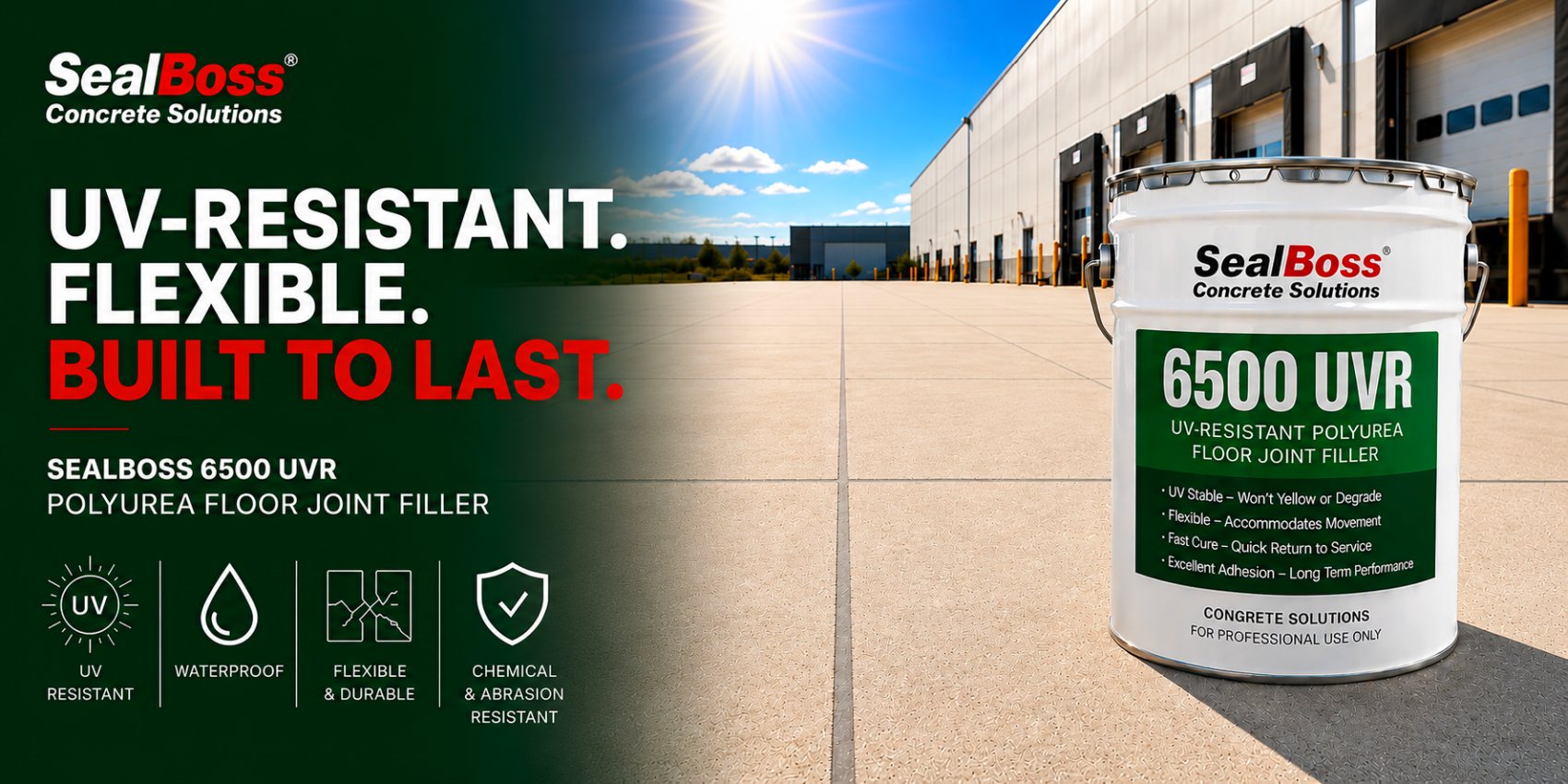
UV-Resistant Polyurea Floor Joint Filler | SealBoss 6500 UVR

UV-Resistant Polyurea Joint Filler

Product packaging and labeling shown are illustrative and may vary.

Stop joint edge spalling. Finish fast. Stay color-stable in sun.

SealBoss 6500 UVR represents the newest generation the latest advancement in polyurea joint fillers, specifically engineered to resist fading and color change under the influence of ultraviolet light.

SealBoss 6500 UVR is a rapid-setting, self-leveling polyurea joint and crack filler built for heavy-duty concrete floors—with added UV resistance for sunlit areas.

Quick spec snapshot – Two-component polyurea, 1:1 ratio, self-leveling, 100% solids

Key Features and Applications

Utilized for the filling of construction and control joints, SealBoss 6500 UVR is frequently used within the scope of industrial warehouses and other commercial concrete floors. Its application is crucial in enhancing joint longevity, aiding in the protection of joint edges from premature spalling, and in preventing deterioration under the pressure of heavy loads and frequent wheel traffic.

UV-Resistant Polyurea Floor Joint Filler Durability

SealBoss 6500 UVR polyurea joint filler distinguishes itself with its UV-resilience, quick-setting nature, and its capacity to withstand heavy duty demands. It’s a semi-rigid, flexible polyurea formulation, designed to uphold the highest of standards while still being offered at an impressively competitive price point.

  • UV Resistant (UVR): Better color stability in sunlight-exposed areas
  • Fast turnaround: Tack-free in ~5–15 minutes (temperature dependent)
  • Reopen quickly: Typically back to traffic in ~60 minutes
  • Tough + flexible: Allows slab movement while protecting joint edges from damage
  • Self-leveling & low odor: 100% solids, VOC-free, essentially odorless
  • Wide temp range: Cures from -20°F to 130°F
  • Jobsite-friendly: Reduced moisture sensitivity; petrochemical resistant

Ideal for Class 5–9 concrete floors and other heavy-duty surfaces, including:

  • Warehouses, manufacturing, bottling/canning, airports
  • Food processing, cold storage/freezers
  • Areas with forklifts, steel/urethane wheels, and high point loads

SealBoss 6500 Polyurea Colors

Reproduction of colors. Actual colors may vary.

6500 UVR

6500 Standard

Light Grey

Dark Grey

Sandy Grey

Clear / Unpigmented

Rapid Curing and Application

The SealBoss ® 6500 UV-Resistant Polyurea Floor Joint Filler employes the most advanced polyurea technology available. The SealBoss 6500 UVR joint filler sets quickly, allowing for rapid project turnaround. This technology is notable for its exceptional advantages and attributes, which encompass rapid application, fast curing times, and adaptability to low-temperature installations.

The inherent durability of the SealBoss ® 6500 line, combined with the simplicity and swiftness of its application, leads to a repair solution that surpasses others in terms of both quality and economy. This makes it an optimal choice for both contractors seeking efficiency and project owners desiring cost-effective results.

Environmental and Safety Benefits

The SealBoss 6500 line, including the UVR variant, distinguish themselves further by being self-leveling, composed entirely of solids, free from solvents in their formulation.

This makes the product environmentally friendly and with essentially no emission of volatile organic compounds (VOCs), contributing to a safer application process and a healthier environment. The joint fillers are also low-odor and do not emit harmful fumes, making them suitable for outdoor and indoor applications where air quality is a concern.

Joint fillers within this line come in a standard gray as well as a variety of customizable colors. This ensures that they can satisfy both functional requirements and aesthetic preferences.

Conclusion

The SealBoss 6500 UV-Resistant Polyurea Floor Joint Filler is a superior solution for concrete joint filling, offering a unique blend of UV resistance, rapid curing, and flexibility.

Its environmentally friendly formulation makes it an optimal choice for a wide range of applications, from industrial floors to commercial spaces exposed to harsh environmental conditions.

By choosing SealBoss 6500 UVR, contractors and project owners can ensure durable, long-lasting, and visually appealing joint repairs that stand the test of time.

Minimum Orders For Colored SealBoss 6500 Joint Filler Product are:
– 10 Gallons For Bulk Orders
– 60 ea. Cartridge Orders

Custom Colors are available and made to order – please contact your technical sales rep for details

Color Chart Page

Contact Your SealBoss ® Technician

Field Reference Sheets for Injection Grouting & Waterproofing

Equipment shown is illustrative and may vary.

Field Reference Sheets
Injection Grouting & Waterproofing

Quick Guideline Reference Sheets

Common Injection Grouting and Concrete Waterproofing Applications

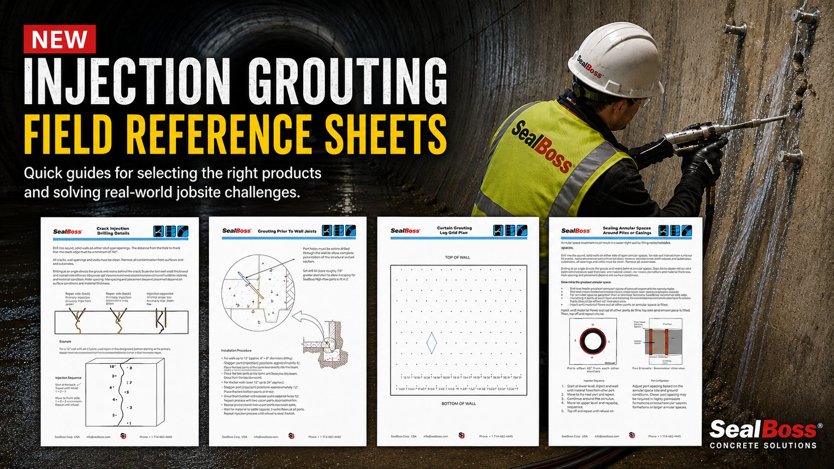
SealBoss has published four practical field reference sheets to support contractors, applicators, engineers, waterproofing professionals, and facility maintenance teams with common injection grouting and leak-sealing applications.

These reference sheets are designed as quick visual guides for selected application conditions, including drilling layout, packer positioning, injection sequencing, and general field orientation.

They are not intended to replace the comprehensive technical information available. Detailed product data, system information, application guidance, technical documents, videos, and supporting resources are available online at sealboss.com.

SealBoss encourages contractors and specifiers to use the website search function to locate additional product information, application details, technical data sheets, safety data sheets, equipment information, and related grouting resources.

New Field Reference Sheets Available

Crack Injection Drilling Guideline

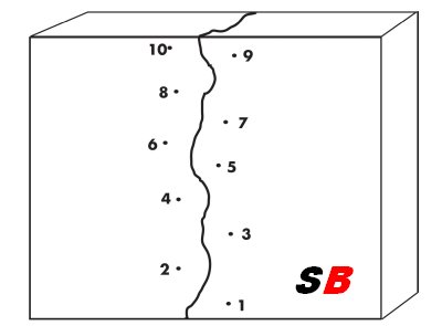
The SealBoss Crack Injection Drilling Guideline is a quick reference sheet showing typical angled drilling concepts for crack injection work.

The illustration helps demonstrate how angled drill holes can be used to intersect a crack inside the concrete element, supporting improved grout penetration and material travel along the crack.

Pdf click here

Grouting Floor-to-Wall Joints Guideline


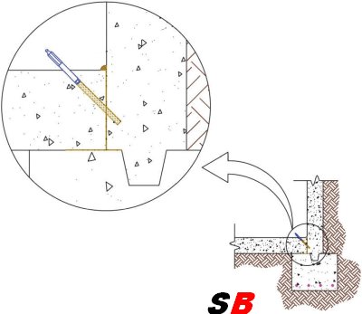
The SealBoss Grouting Floor-to-Wall Joints Guideline is a visual field reference for slab-to-wall joint injection conditions.

This type of detail is commonly encountered in below-grade structures, containment areas, basements, tanks, utility structures, and other concrete assemblies where water migration may occur at the wall/slab interface.

The reference sheet includes basic drilling angle concepts, packer placement orientation, port spacing notes, pre-wetting considerations, and injection observations such as port-to-port material travel.

Pdf click here

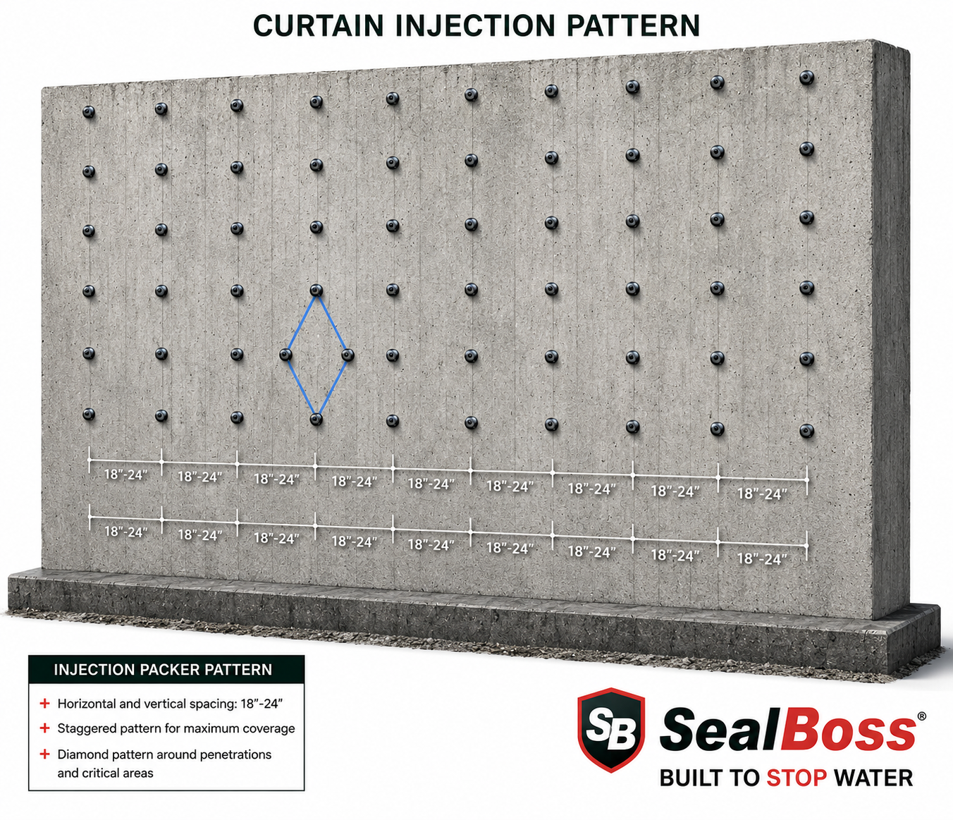
Curtain Grouting Layout Plan Guideline

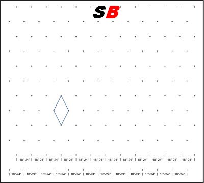
The SealBoss Curtain Grouting Layout Plan Guideline is a layout reference sheet for curtain grouting applications.

Curtain grouting is often used when water intrusion must be addressed from the negative side of a structure by creating a grout barrier behind or within the concrete element.

The sheet illustrates a grid-style drilling pattern that can assist with planning injection points and organizing the work area before grouting begins.

Pdf click here

Sealing Annular Spaces Around Pipes or Conduits Guideline

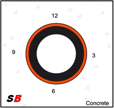
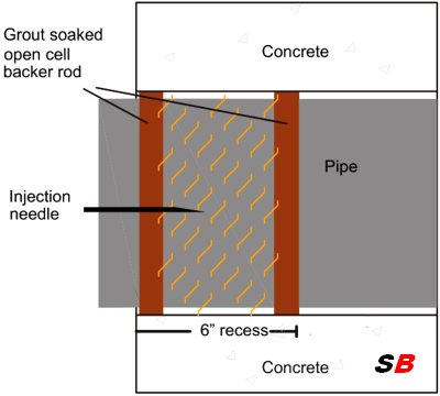
The SealBoss Sealing Annular Spaces Around Pipes or Conduits Guideline is a field reference sheet for pipe penetrations, conduit penetrations, and similar annular-space leak-sealing conditions.

The sheet outlines a basic workflow using saturated oakum or open-cell backer rod, followed by polyurethane grout injection behind the packing material.

It also includes injection-position references around the pipe, observation-point concepts, equipment notes, and pump loading and cleanup guidance.

Button:
View Annular Space Sealing Reference Sheet

Pdf click here

More Technical Information Is Available Online

These SealBoss reference sheets are intended as practical jobsite orientation tools. They can support planning, crew communication, application discussions, and project documentation for concrete crack injection, joint grouting, curtain grouting, and annular-space sealing.

For complete product information and application support, users should explore the broader SealBoss online resource library.

Use the SealBoss website menu and search function to find additional information on:

Injection grouts
Injection packers
Accessories
Injection pumps
Videos
Comprehensive Technical Information

Need Help Selecting the Right Injection Grout, Packer, Pump, or Application Method?

Contact SealBoss Technical Support

Related Articles

Contact Your SealBoss ® Technician

Curtain Injection Grouting | Hydrophilic Injection Gel Foam FlexGel

SealBoss Curtain Injection Pattern

SealBoss ® FlexGel

  • Curtain Injection Grouting
  • Bladder Injection | Blanket Injection
  • Leak Sealing Gel
  • Soil Permeation & Stabilization
  • Concrete Crack Seal Gel
  • NSF Drinking Water Contact Gel

SealBoss FlexGel Hydrophilic NSF LV Gel

Curtain Injection Grouting | SealBoss® FlexGel Hydrophilic Polyurethane Foam/Gel

SealBoss® FlexGel is an advanced, single-component hydrophilic polyurethane foam/gel engineered specifically for curtain injection grouting applications. Its superior penetration, flexibility, and durability make it ideal for sealing leaks, soil stabilization, concrete crack repairs, and creating waterproof membranes.

Key Applications of SealBoss® FlexGel – Hydrophilic Polyurethane Injection Grout:

  • Curtain Injection Grouting: Forms a reliable waterproof barrier around concrete structures.
  • Bladder Injection / Blanket Injection: Ideal for sealing underneath slabs, effectively creating a flexible, durable membrane.
  • Leak Sealing Gel: Rapidly reacts upon contact with moisture to seal active leaks.
  • Soil Permeation & Stabilization: Strengthens soil structures by incorporating absorbed resin into the surrounding environment.
  • Concrete Crack Seal Gel: Effective for sealing concrete cracks through controlled injection.
  • NSF/ANSI 61 Certified: Suitable for use in potable water systems, ensuring compliance with drinking water safety standards.

Exceptional Properties and Benefits:

SealBoss® FlexGel offers superior hydrophilic properties. At a mixing ratio of 1 part FlexGel to 10 parts water by volume, the product achieves an exceptionally low viscosity of approximately 50 cps, ensuring outstanding penetration and distribution throughout injection areas.

The remarkable swelling capacity of FlexGel upon contact with water distinguishes it significantly from hydrophobic alternatives, enabling the formation of a robust waterproof gel barrier. When used neat, FlexGel rapidly expands upon encountering minimal moisture, adapting its reaction from foam to gel based on the counter-pressure applied.

Stable Performance Under Varied Conditions:

SealBoss® FlexGel is engineered for stability and endurance. Once cured, it maintains its integrity even in fluctuating moisture environments, easily withstanding repeated wet/dry cycles without degradation.

Why Choose SealBoss® FlexGel:

  • High-Quality Hydrophilic Formula: Exceptional absorption and sealing capabilities.
  • Ease of Application: Single-component, easy mixing, and reliable performance.
  • Durable and Flexible Membrane Formation: Resilient protection that adapts to structural movements and environmental changes.
  • NSF Drinking Water Approved: Certified safe for direct contact with drinking water.

Contact SealBoss for More Information:

For detailed product specifications, application advice, or to inquire about ordering SealBoss® FlexGel Hydrophilic Polyurethane Foam/Gel, please contact our expert team at SealBoss. We are here to support your waterproofing, leak sealing, and stabilization projects.

SealBoss FlexGel Data Page

SealBoss FlexGel is a single component hydrophilic chemical injection grout.

FlexGel is our high quality hydrophilic gel product. It can incorporate large amounts of water when premixed or react with just very small amounts of moisture similar to our hydrophobic foam products.

FlexGel is very stable when cured and can endure dry environments post cure without failure.

FlexGel is an excellent choice for curtain and bladder injection as well as underneath slabs which we refer to as blanket injection. The product can form a flexible and durable membrane along the positive side of the concrete structure which withstands wet and dry cycles very well. In addition, Flexgel resin absorbed by dirt acts as a strong soil stabilizer.


The product can also be used for crack injection in certain applications.

Inquire more about SealBoss FlexGel when you call us here at SealBoss. Your representative will be happy to help you out.

Chris Coderre
National Sales Manager
Contact Your SealBoss ® Technician

SealBoss Injection Job Checklist

Concrete Injection Job Checklist

Confirm the material, pump, packers, site conditions, documentation, cleanup plan, and field records before injection begins.

This planning checklist connects products, equipment, and method without treating epoxy, polyurethane, and acrylate injection as one universal procedure.

Use This as a Readiness Checklist

Use this page to plan mobilization, confirm field readiness, organize quality-control observations, and document the work. It does not replace the current product data sheet, SDS, application guideline, equipment manual, project specification, or direction from a qualified technical representative or design professional.

Quick Guide: Crack Injection Procedure

Crack injection requires careful preparation, the correct material and equipment, and close observation throughout the work. Use this guide as a general sequence alongside the job checklist. The exact procedure depends on the injection material, crack condition, structure, equipment, and approved application method.

1. Prepare Equipment and Protective Gear

Gather the required injection material, pump, hoses, applicator, packers or ports, couplers, tools, cleaning materials, and spare components. Confirm personal protective equipment and jobsite safety requirements from the current SDS, project safety documents, and site rules.

2. Inspect and Document the Injection Area

Examine the crack, joint, or leak area before work begins. Record visible conditions, moisture or active water, access limitations, possible material exits, and adjacent areas that may require protection.

3. Prepare the Crack and Surrounding Surface

Remove loose material, dust, debris, coatings, or contaminants as required by the approved procedure. Preparation methods vary by injection system and substrate condition.

4. Install Packers or Ports

Select and install the specified mechanical packers or surface-mounted ports. Packer type, drilling angle, depth, and spacing must follow the approved application method and actual project conditions.
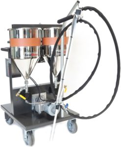
5. Prepare the Injection Material

Confirm the exact product and component system. Follow the current product data sheet and application instructions for conditioning, mixing, proportioning, accelerator use, and equipment setup. Do not substitute components or alter ratios without technical authorization.

6. Apply a Surface Seal When Required

Some injection methods—particularly certain epoxy procedures—may require the exposed crack surface to be sealed between ports. Use the specified material and allow it to develop the required condition before injection.

7. Begin the Injection

Start at the location identified in the approved injection sequence. Connect the pump to the first packer or port and proceed according to the product, equipment, and application instructions. The correct sequence may vary with crack orientation, water condition, structure, and injection objective.

8. Monitor the Procedure

Observe material flow, pressure response, packer or port stability, returns at adjacent locations, and any unintended leakage or discharge. Stop and request technical review when conditions differ materially from the approved plan.

9. Allow the Material to React or Cure

Follow the current product documentation for reaction, cure, hold, or waiting requirements. These periods vary significantly among epoxy, polyurethane, and acrylate systems.

10. Remove or Finish Packers and Ports

Remove, cut back, or leave packers and ports in place as directed by the approved procedure. Patch or finish the injection locations according to the project requirements.

11. Clean Equipment and Manage Waste

Thorough equipment cleaning is essential. Follow the current SealBoss cleaning instructions for the specific material and equipment system, and handle or dispose of all waste and cleaning materials in accordance with the SDS, site requirements, and applicable regulations.

12. Complete the Final Inspection

Document the completed work, material use, injection observations, and any remaining conditions. Acceptance should be based on the project specification and the criteria established by the responsible contractor, technical representative, or design professional.

Important: This quick guide is a general planning reference. Always follow the current SealBoss product data sheet, SDS, application guideline, equipment manual, and project-specific requirements for the exact material and system being used.

Stop before starting: Product and method selection must be based on the repair objective and actual project conditions.
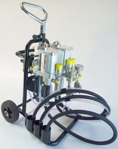
Material

Confirm the exact product variation, components, condition, current documents, and approved cleaning materials.

Equipment

Match the pump, hose, applicator, packers or ports, couplers, spares, and power requirements to the system.

Method

Use the approved preparation, installation, monitoring, shutdown, and field-record procedure for the application.

Project Information

Complete these fields before mobilization or at the pre-job meeting.

1. Confirm the Repair Objective

2. Documents to Have at the Jobsite

3. Materials and Components

4. Pump, Hose, and Applicator Readiness

5. Packers, Ports, and Drilling Equipment

6. Jobsite and Safety Readiness

7. Crack and Injection-Area Assessment

8. Final Pre-Injection Check

9. Injection Quality-Control Record

10. Shutdown, Cleanup, and Closeout

Stop Work and Request Review When

Product-System Verification

Use these prompts to verify readiness. They are not universal application instructions.

Polyurethane Leak-Seal Injection

Epoxy Crack Injection

Acrylate or Gel Injection

Build the Complete Injection System

A prepared injection crew needs more than the resin.

Products

Equipment

Field Support

Review Current Technical Resources Before Mobilizing

Review the current documents for the exact product and equipment system. Contact a SealBoss technical representative for application-related product, pump, packer, and system information.

Products, Equipment, and Training

Pump & Equipment Support

Pump & Equipment Support

Troubleshooting, Maintenance Guidance, Parts, and Training

Technical support for professional users of SealBoss pumps and equipment.

Support for Professional Pump Owners and Operators

When a pump is not delivering material as expected, the fastest useful starting point is accurate information: the equipment model, the material being dispensed, the observed symptoms, and the recent cleaning or maintenance history.

SealBoss technical representatives can help review the available information and direct professional users to the relevant pump page, data sheet, manual, parts information, or training resource. Material and equipment suitability must be confirmed for the intended product and project conditions.
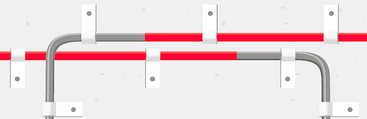
Troubleshooting and Equipment Questions

Discuss operating symptoms, material-flow concerns, pump configuration, and the current documents needed for further review.

Parts and Service Direction

Identify the pump model and affected component so the SealBoss team can help determine the appropriate next step. Mechanical and electrical service is restricted to qualified, trained technicians.

Training and System Support

Request on-site consultation or systems training covering the pump, material, applicator, cleaning, and related workflow.

Prepare These Details Before You Contact Support

  • Pump model and serial number, when available
  • Material name, component ratio, and current technical and safety documents
  • A clear description of the symptom and what changed before it occurred
  • Photos or a short video of the pump, tanks, hoses, applicator, and control display
  • Recent cleaning and maintenance history, including products used
  • Jobsite location and schedule constraints

Before Any Service Work

Service boundary: Service to mechanical or electrical components must be performed by trained professionals. Equipment must be disconnected from all power sources before service. Follow the current equipment manual and the material technical data sheet and SDS.

Field Support Example: JointMaster Pump Diagnosis

A Midwestern contractor reported difficulty dispensing a polyurea joint filler on a time-sensitive project. A local SealBoss technical representative inspected the JointMaster joint-fill machine in Kansas City.

The original field report documented hardened or crystallized material in the equipment and a seized ISO-side gear pump. The service included diagnosis, purging, cleaning, and installation of a replacement gear pump.

Documented result: The original report states that the pump was returned to operation in approximately two hours.

Use the Current Manual for Cleaning and Maintenance

The current JointMaster Pro2 G3i Digital manual states that material should not be left in the tanks over extended periods and provides the applicable cleaning, maintenance, and trained-service requirements.

Review the current manual and the technical and safety documents for the material being dispensed before operation, cleaning, or service. Equipment configurations and current models may vary.

Curtain Injection In Pictures

SealBoss Curtain Injection Pattern

Curtain / Bladder Injection - Curtain Wall Grouting Method

Water intrusion is a persistent challenge for below-grade concrete structures, where traditional patching and surface sealers often fall short. The failures of these surface-applied remedies—such as patches, liquid sealers, and membrane applications—stem from their inability to address the root causes of leaks. These methods provide only temporary relief, leaving structures vulnerable to recurring hydrostatic pressure and ongoing water damage.

Curtain wall grouting, including advanced techniques like curtain and bladder injections, offers a reliable, long-term solution to these challenges. Unlike surface treatments, these methods work by creating a robust waterproof membrane and water barrier behind the structure. This approach not only seals cracks and cold joints from within but also fortifies the structure against future water intrusion.

By injecting specialized grouts through the structure to form a protective layer on the positive side, curtain injection ensures a comprehensive and lasting seal. Whether applied through stage grouting or other targeted injection methods, this professional approach delivers durable protection, minimizing service interruptions and maximizing cost-effectiveness in the long run.

Curtain Injection in Pictures SealBoss

Curtain / Bladder Injection is the Reliable Way to Waterproof Your Below Grade Concrete Structure

Why Patches and Liquid Sealers Often Don’t Stand the Test of Time

Experiencing the frustration of failing patches and paint applications on damp, actively leaking, below-grade structures is something many of us can relate to.

These are typically failed attempts to block hydrostatic water intrusion using surface-applied remedies that serve as temporary solutions at best.

Interior patches and membrane applications, while seemingly addressing the problem, often don’t tackle the root cause and rarely provide a lasting waterproofing resolution.

A Professional Approach to Curtain Injection:

Sealing Cracks Permanently and Establishing a Waterproof Membrane and Water Barrier behind the Structure

Water leakage via cold joints, cracks, and other irregularities in concrete can frequently only be effectively and permanently sealed using advanced injection techniques, such as curtain, bladder, and stage grouting injection methods.

The SealBoss Injection Product offers a professional solution to these issues, filling and sealing the cracks from the inside out. This product is injected through the structure, forming a membrane on the structure’s positive side, thus providing a more effective and lasting waterproofing solution.

The Art of Stage Grouting Technique

In complex grouting scenarios, the stage grouting technique is often the favored approach. This process entails a strategic series of injections carried out in a staged manner, utilizing lower volumes of product in each application.

Each stage of this meticulous process is allowed sufficient time to react, allowing the grout to solidify and establish a natural barrier before proceeding with the subsequent stage of grouting. This carefully phased and controlled deployment not only elevates the overall efficacy of the grouting operation but also ensures thorough and consistent coverage along the exterior of the wall.

Comparative Cost Analysis of Injection Grouting Sealing Methods

Understanding the financial impact of various sealing techniques is essential for making cost-effective decisions. Below is a comparison.

Crack Injection

Direct Costs: Moderate for materials and labor, product is injected directly into the cracks, joints, and voids. Low for equipment.
Indirect Costs: Minimal, as the method is fastest and causes little service interruption.

Curtain Grouting

Direct Costs: Higher for materials and labor, product is injected through the structure into the substrate behind, which results in higher material consumption. Packers are set in distinctive patterns. Moderate for equipment.
Indirect Costs: Higher, due to the lengthier process of preparation and product pumping, which can lead to more significant service disruptions.
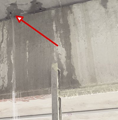
Links

Curtain Injection Grid Pattern
SEALBOSS-CURTAIN-INJECTION
Packer Installation in a Grid Pattern
BASEMENT-WATERPROOFING-PRODUCTS-SEALBOSS
Excellent Hairline Crack Penetration
SEALBOSS-1510-PERMEATION
Bladder Injection Process
Popular Posts
More Posts
Archives
Categories
Scroll to Top