

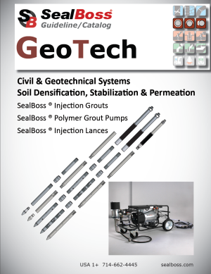


Crack Injection Guideline
1 - 2 - 3 at 45 Degree
Crack Injection Guideline
1 - 2 - 3 at 45 Degree
Injecting Trust - One Crack at a Time
Introduction
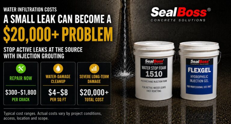
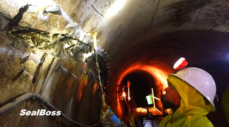
Cracks in concrete structures are more than just cosmetic issues—they can compromise integrity, allow water intrusion, and accelerate rebar corrosion. The SealBoss 1-2-3 at 45 Degree Crack Injection Guideline provides a proven, systematic approach to crack injection that ensures effective leak sealing and structural protection. By following three critical steps—preparing and mapping packer placement, installing the packers, and executing the injection at a 45-degree angle—contractors can achieve durable, high-quality results. This article outlines best practices, technical details, and important considerations to help professionals optimize their injection process and maximize success, one crack at a time.
The SealBoss 1-2-3 at 45 Degree Crack Injection Guideline
- Step 1 – Preparing and Mapping Out Packer Placement
- Step 2 – Installing the Packers
- Step 3 – Executing the Injection Process
- 45-Degree Angle – Recommended Packer Angle / Positioning Guideline
Optimal Techniques and Considerations
The SealBoss 1-2-3 at 45 Degree Injection Guideline highlights the three fundamental steps of the injection process while emphasizing the importance of a standard 45-degree angle for packer placement. Although the 45-degree angle is a widely accepted practice, certain situations may require deviation from this rule, as discussed in this article.
Additionally, it is advised to target each injection port three times during the injection procedure – as a general rule – to ensure adequate density and penetration of the chemical grout within the structure. Injection Packers that persistently absorb product should be injected repeatedly, as many times as needed, to ensure a lasting seal.
Injection Packer Spacing
Mechanical injection packer spacing, also referred to as port spacing, in the context of leak-seal crack injection is contingent upon several site-specific conditions, such as crack width, substrate thickness, water flow, and product properties.
In numerous instances, an 8-inch (20 cm) to 1-foot (30 cm) on-center spacing serves as a suitable initial distance. Hairline cracks necessitate tighter spacing, as the product is less capable of traveling far. Consequently, the tighter the cracks, the closer the required spacing.
Injection Packer Placement
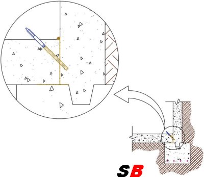
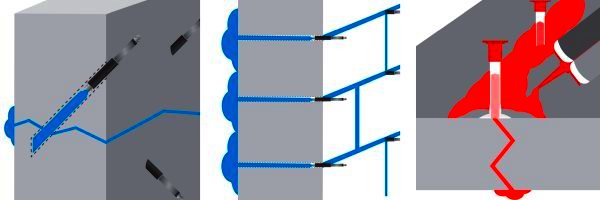
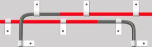
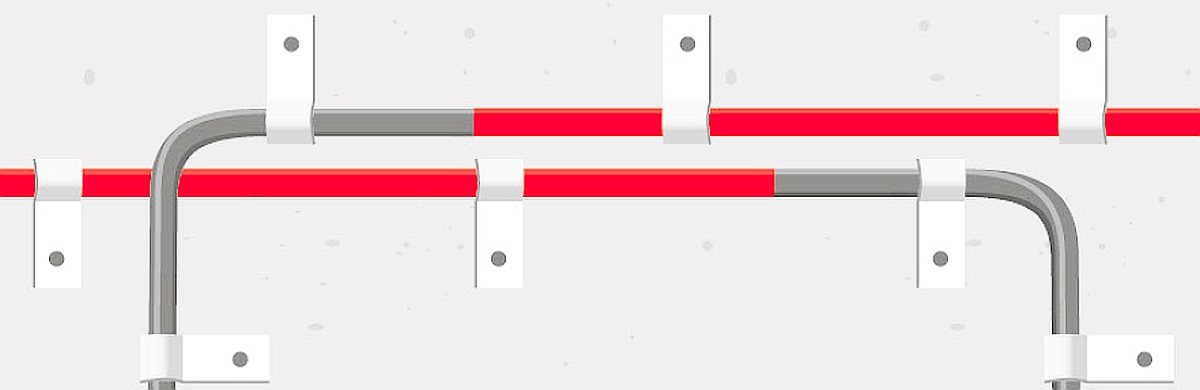
In the majority of cases, injection packers should be arranged in a staggered manner by alternating drill holes to the left and right of the crack while drilling at a 45-degree angle toward the crack, thereby forming a stitch grouting pattern. This method enhances the likelihood of intersecting the crack during drilling and reduces the probability of concrete cracking and spalling during packer installation or the high-pressure injection process. Injection should commence from the bottom and proceed upward.
45 Degree Angle Drilling and Packer Placement
The optimal method for packer placement involves positioning at a 45-degree angle. For structures with a thickness exceeding 6 inches (12-15 cm), SealBoss recommends a 45-degree angle as the most effective strategy for intersecting the crack at the midpoint of the structure. This is accomplished by initiating drilling a few inches to the left or right of the crack at an angled trajectory toward the crack itself, rather than drilling directly into it. This technique enables the requisite “inside-out” product flow for optimal crack penetration.
For instance, in a 10-inch thick concrete wall, one should move approximately 4-5 inches (8-10 cm) away from the crack and drill at a 45-degree angle toward it to attain the desired target. Initiating drilling with a straight entry and subsequently angling the drill at the required angle is beneficial.
Typical drill spacing along the crack’s surface ranges between 6-12 inches (10-20 cm) depending on the crack’s thickness. Hairline cracks necessitate closer spacing than larger cracks, as the material will not travel as far. Stagger drill holes from one side of the crack to the other, intersecting the crack during drilling.
Optimizing Drill Hole Distance from the Crack
When determining the spacing of drill holes from a crack for chemical grout injection, it is essential to understand the relationship between the hole’s distance from the crack and the depth at which it intersects the crack. Here is a detailed explanation:
- Depth of Intersection: The greater the distance between the drill hole and the crack, the deeper is its intersection with the crack inside the structure, leading to a deeper point of injection.
- Considerations for Thicker Structures: In thicker structures, a deeper injection point is usually favored. Yet, it is essential to factor in the drill bit’s length and reach, as they play a crucial role in determining the optimal distance for the drill hole. Always allow for a margin of error and ad at least a margin of 2 inches to the calculated drill bit reach needed.
- Avoiding Dead-End Drill Holes: A drill hole that misses the crack cannot facilitate the injection of the chemical grout into the structure. Such holes are termed “dead-end drill holes” and are ineffective for the purpose of grout injection.
Determining the Required Minimum Length for a Drill Bit
When drilling at a 45-degree angle, we encounter a specific triangle called the 45-45-90 triangle, which follows the principles of the Pythagorean theorem.
In this 45-45-90 triangle, both legs, marked “X” are of equal length. X is the distance the drill hole is placed away from the crack. Therefore, when drilling at a 45-degree angle, if we assume the crack is perpendicular to the surface, the depth at which the drill hole intersects the crack will be the same as the distance of the drill hole from the crack. To determine the minimum drill depth, or the distance from the drill hole surface to the crack, use the formula:
Distance from crack X √2, which is approximately 1.414.
To simplify and account for variations we use the factor 1.5 to calculate the absolute minimum drill hole depth necessary to intersect the crack.
For a 5-inch distance from the crack, the calculation would be: 5 × 1.5 = 7.5 inches. Therefore, the drill hole should be at least 7.5 inches deep to guarantee intersection with the crack for injection in near perfect conditions.
For a 6-inch distance from the crack, the calculation would be: 6 × 1.5 = 9 inches. Therefore, the drill hole should be at least 7.5 inches deep to guarantee intersection with the crack for injection in near perfect conditions.
Now add at least 2 inches of drill bit reach to the calculation. It is essential to remember that not all cracks might run perfectly perpendicular to the surface, so always consider the specific conditions of your project.
In summary, while determining the placing of drill holes, it is important to balance the desired depth of injection with the capabilities and reach of your drilling equipment to ensure effective grout injection.Remember, the effective reach of a drill bit and its actual length differ.
Always ensure your drill bit has the necessary length to effectively intersect the crack!
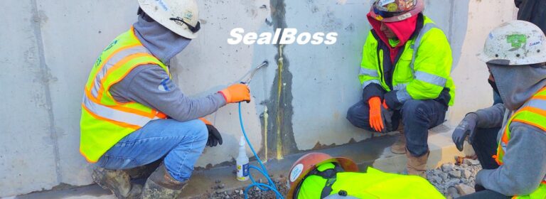
General Injection Packer Preparation – Drill and Flush
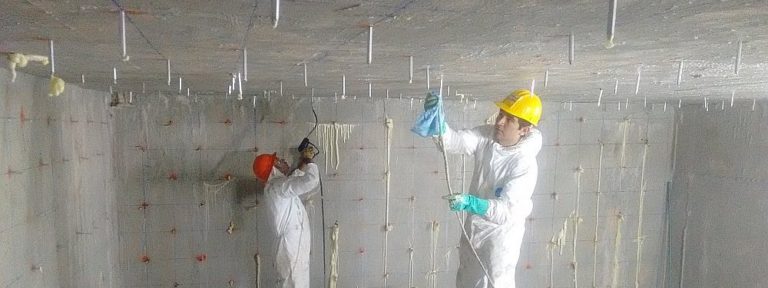
Safety Gear
Consistently wear appropriate protective gear and goggles, adhering to data sheet and SDS instructions.
Cleaning
If required, clean the crack or joint’s face using a wire brush, pressure washing, or similar method. A clean surface facilitates the identification of cracks and problematic areas.
Spacing
Mechanical injection packer spacing, also known as port spacing, is contingent upon various site conditions such as crack depth and width, substrate thickness and state, water flow rate, and the product’s physical and chemical properties.
An 8-inch (20 cm) to 1-foot (30 cm) on-center spacing is suggested for the majority of situations. Hairline cracks necessitate tighter spacing compared to wider cracks. The tighter the cracks, the closer the required spacing, as the product must travel deeply enough into the structure to form a permanent seal.
Determine the spacing, pattern, and depths of the drill holes. Based on the crack’s width, space the packers at a distance of approximately 6-18 inches (10-45 cm). The tighter the cracks, the closer the required spacing. Hairline cracks result in limited water stop and leak-seal grout travel, necessitating tighter packer spacing, while wider cracks permit easier flow and broader packer spacing.
Stagger drill holes from one side of the crack to the other (left/right), thus forming a stitch grouting pattern. This technique increases the chances of intersecting the crack during drilling while decreasing the likelihood of cracking and spalling the concrete during packer installation and the high-pressure injection process.
Typically, injection should begin at the bottom and move upward, pushing the product against gravity and water flow, thereby achieving a higher density in the process.
Exceptions to the 45 Degree Injection Rule – Straight Drilling
As with any rule, the catchy SealBoss 1-2-3 at 45-Degree Rule has its limitations and exceptions. Here are three notable examples:
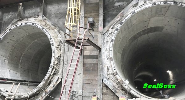
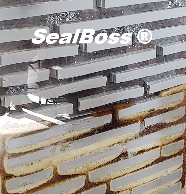
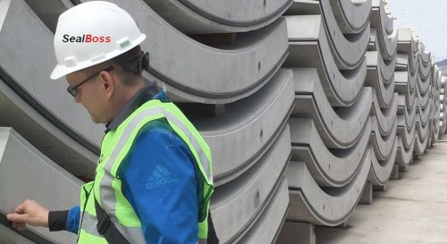
- Drilling into Joints
Drilling into joints, such as concrete tunnel segments, is predominantly performed in a straight manner. - Thinner Stuctures
Concrete structures with a thickness of less than 6 inches may not permit angle drilling, as this can result in cracking and spalling of the concrete. - Badly Deteriorated Substrate
Similar issues can occur in severely deteriorated concrete substrates and in concrete of inferior quality. In such situations, it is recommended to drill and install packers directly into the crack without completely penetrating the structure.
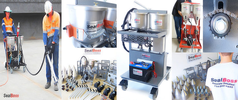
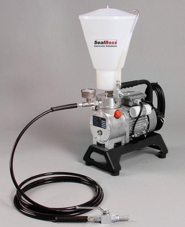
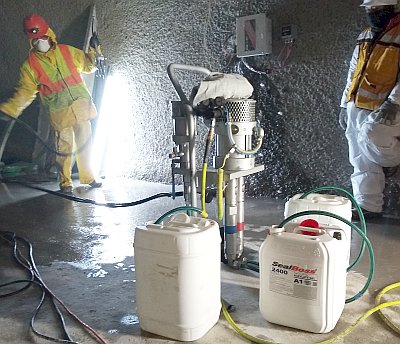
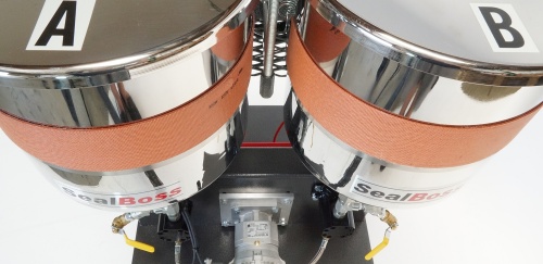
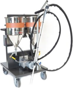
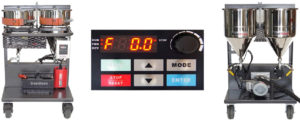
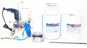
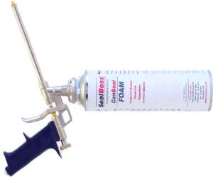
SealBoss offers an extensive range of injection equipment and pumps to accommodate your project. Consult a SealBoss technician for detailed information and assistance. We look forward to helping you with your project.
Drill Dust
When drilling deeper holes, periodically extract your drill bit to remove drilling dust and prevent your drill from binding up.
Rebar
Most concrete structures contain rebar steel reinforcement to provide structural strength. In an ideal, crack-free structure, concrete protects the rebar from corrosion by insulating it from moisture and air while maintaining a high pH environment. However, when cracks form, this shield is compromised, allowing air, environmental gases, and water to cause carbonation, and subsequently corrosion of the rebar, which forms rust expands to expands its original volume. The expansion of rusted rebar exerts high forces against the concrete, resulting in further deterioration, cracking, and spalling. Chemical grout injection protects rebar and can mitigate these processes.
Rebar often slows down the drilling process. When your drill bit contacts rebar, the sound changes, the quantity of drilling dust may be reduced, and the progression slows down or may even stop.
Some drill bits enable drilling through rebar, although this is generally not recommended and may even be prohibited, as it can weaken the concrete structure. In such cases, relocating the drill hole is the only option. If you repeatedly hit rebar, consider drilling straight into the crack. Dead-end drill holes, the holes that are not used for injection, must be patched and sealed before injection to prevent leakage.
Flushing / Cleaning Drill Holes Prior to Injection
Overview
Drilling debris can thicken the product during injection, resulting in higher injection pressures and reduced penetration in fine cracks. It is best practice to remove concrete dust and debris from the drill holes by flushing with a water hose until clean water is observed. You can use a water hose to flush debris from the hole.
Vacuuming out the dust can also be helpful if flushing is not possible.
Blowing out the debris is another option; however, be aware that dust can be an inhalation hazard, and appropriate gear is mandatory.
Flushing / Cleaning of holes is not necessary if water is actively running from your drill holes.
Drill Hole Water Flushing Detail
Low Pressure Flush
For low-pressure flushing, simple tools like a plastic water squeeze or spray bottle suffice. This method can remove debris from the drill hole and introduce water into the drill hole.
If available on site, a water hose can be used to flush the drill holes.
Using a Dedicated Flushing Water Pump
A dedicated water injection pump is suitable for both low-pressure drill hole flushing with a hose and on-site pressure crack flushing with water through injection packers.
While drill hole flushing serves to remove debris from the hole only, high-pressure water flushing can provide insights into material flow, expected product penetration distance, and introduce moisture to enhance product reactivity.
For such high-pressure applications, a dedicated water flushing pump is essential.
After clearing the drill hole, an injection packer is positioned. The water pump is then linked to channel water under high pressure via the injection packer into the into the crack, flushing it in the process.
If the crack remains unresponsive to taking on water, it might indicate that the hole is not linked to the crack. In such cases, a new drill hole has to be established and retested with water.
While high-pressure flushing is not typically required for most injection projects, it can offer benefits in specific scenarios.
It is imperative not to use the same pump for water injection that you use for dispensing polyurethane resin. Given that polyurethanes are activated by water, even the slightest moisture can result in pump malfunction.
Final Thoughts
Equipment limitations may render flushing infeasible; however, most injections will succeed without additional water introduction, even in seemingly dry crack environments. If the product does not immediately contact water, it will cure over time as natural moisture in the concrete stimulates curing and hardening, potentially at a slower pace.
Additional Injection Packer Installation Recommendations
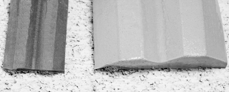
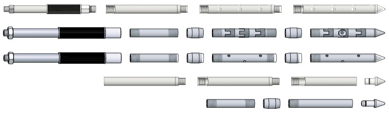
Mechanical Packer Fundamentals
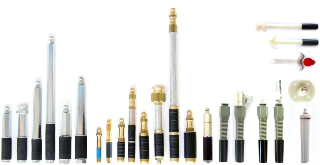
For optimal performance, packers and drill holes must possess adequate quality to endure injection pressures without leakage or displacement within the crack. Notably, even superior packers may rupture or leak under certain conditions. SealBoss Mechanical Packers, available in various sizes and designs, are recommended for pressure injection. These packers feature a threaded shaft with a rubber base; upon insertion, tightening the shaft compresses the rubber within the drill hole, generating a compression seal. Standard packer diameters range from 1/4 to 3/4 inches, with industry norms between 3/8 and 5/8 inches. In poured concrete substrates, drill holes serve as solid channels directing resin to the crack, enabling the use of shorter packers. In substrates with potential voids, such as block walls, stone, and brick, SealBoss advises employing longer packers to ensure a definite grout delivery channel to the crack being sealed.
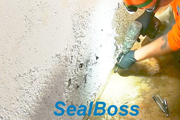
Mechanical Packers Installation
To seal against the drill hole, mechanical packers require tightening, which expands the rubber seal. Packers may be pre-tightened by hand to seat the rubber snugly, approximately 1/4 inch (5 mm) inside the drill hole. Correct installation prevents concrete cracking around the drill hole’s exterior. Depending on packer design, using an appropriate ratchet/nut, wrench, or electric driver for tightening is highly recommended. Packers should be securely tightened to withstand injection pressures without over-tightening.
SealBoss Hammer-In Ports are also frequently utilized. These ports are seated using a hammer at moderate force, with an electric driver or hand tool and a suitable socket employed to screw the zerk fitting into the port. Hammer-in ports typically do not achieve the same injection pressures as mechanical packers and should be reserved for applications where maximum injection pressures are not essential.
Packers are typically equipped with a quick-connect system, either a zerk type or button head/slide coupler type.
The zerk type is most prevalent. Applicators must push the coupler over the zerk fitting and maintain alignment with the packer. To disconnect, applicators “break” the connection by pushing the connector sideways.
The button head type provides a more secure connection. The operator slides the coupler on and off the packer, ensuring a secure, tight connection that is less prone to unintended disconnection and leakage. When executed properly, the applicator does not need to hold the coupler in place, a significant advantage in overhead injection and instances requiring large product volumes through one packer.
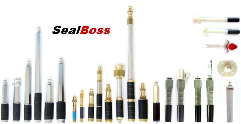
SealBoss offers an industry-leading array of injection packers and ports for diverse situations and requirements. Contact a SealBoss representative for packer recommendations tailored to your project.
Injection Products
Before You Start Injection
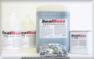
Before injection, review the product datasheet instructions. Ensure your pump is in fully operational condition and completely devoid of moisture before preparing SealBoss Water Stop and Leak Sealing Products for injection.
It is prudent to flush the pump with SealBoss R70 before using any resin/foam grout.
Injection Procedure
When products are prepared for injection, have a cup available to dispose of some resin to ensure purity. Start the pump at the lowest pressure setting. After connecting your grout injection hose to the secured and tightened packers, initiate the injection process.
Use the shut-off valve at the injection hose’s end whenever the hose is moved, remember that some pumps need to be manually stopped .
Starting from the bottom, securely connect your injection line to the packer and commence with the lowest pressure capable of moving resin into the crack. Generally, injection pressure will decrease as material flows, but pressure may need to be increased as products thicken and move into tighter cracks and fissures.
Maintain a slow injection rate as resin begins to show and flow from the crack. Pausing and restarting the process for a minute may be necessary to allow material reaction and thickening.
Monitor consumption rates and cease injection when consumption equals leakage. A typical observation involves reduced water flow from the crack’s face and/or reacting material exiting the crack’s face. This indicates successful penetration and results.
If the product does not advance along the crack, disconnect and proceed to the next port. Applicators must ensure sufficient material is injected into each crack to achieve optimal product density for a durable seal.
It is recommended to inject three to five packers while observing product flow, travel, and refusal from the crack.
Reinjecting those three to five packers—typically up to three times (1-2-3 at 45 degrees) or until product refusal—is crucial. The crack must be adequately filled with as much product as possible without excessive product loss from the crack. Sufficient material consumption and product density in the injected area must be monitored to achieve a solid and successful repair.
Injection Packers that continue to consume considerable product amounts should be injected a third time or as often as necessary to create a permanent seal.
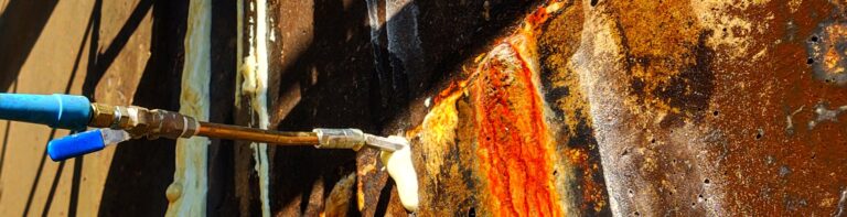
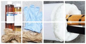
SealBoss Oakum Soakum Technique
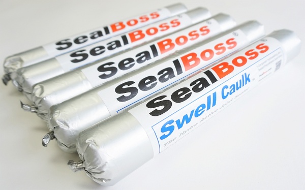
In cases where excessive resin flows out or washes out due to high water flow, resin-soaked SealBoss Oakum can be employed to form a temporary plug, allowing the product time to react, expand, and seal.
Caution: Be prepared for the possibility of product ejection from the structure or around drill holes, as well as packer blowouts. High-pressure injection equipment may cause product to travel further than anticipated, potentially appearing several feet from the injection point. Small cracks may become visible after the injection process.
Quality Injection Job
Injection often necessitates a two-person team, with one individual operating the valve and hose while another manages the pump. Create a dense seal! Inadequate material consumption alone can yield differing results in the same injection application. If the crack is not accepting any product, it may be due to insufficient drilling depth or crack direction on the opposite side. In such cases, drill from the opposite side of the crack and ensure intersection with the crack.
Packer Removal
Once the material has fully cured, packers can be removed by loosening the shaft. Some applicators opt to leave the rubber base in the wall and patch the drill hole, while others remove the entire packer before patching. In certain injection applications, packers may remain in place permanently. This decision is at the discretion of the applicator or owner. A final cleaning of the crack’s face is necessary to remove cured product using a wire brush, pressure washing, or other appropriate methods. The substrate is then prepared for the final finish.
SealBoss R70 Pump Flush for Clean-up
DO NOT CLEAN WITH WATER. If allowed on the job, initially flush all dispensing equipment with a small amount of solvent, such as xylene, to cut the product. Follow this step by generously flushing with SealBoss R70 Pump Flush & Cleaner to protect hoses and lubricate the pump. Avoid using solvents for the final flush, as this can reduce the lifespan of your equipment.
Exception – Equipment for SealBoss 2400 Acrylate is cleaned with water. Consult the data sheet for details.
Inquiries, Comments, or Requests?
Contact us now at 714-662-4445 and request your technical consultant!