


Epoxy Crack Injection Concrete Repair
Epoxy Crack Injection
Concrete Repair
Epoxy Concrete Crack Injection Systems
Epoxy Crack Injection Resin can mitigate problems of cracked concrete with larger and fine cracks. ACI specifies cracks widths that are acceptable in structures under defined conditions. ACI 224R-012 provides a guideline for crack widths for reinforced concrete under service loads for new construction. Crack widths deemed acceptable may range from 0.004 in. (0.1 mm) to 0.016 in. (0.41 mm), and even smaller widths for concrete in wet or aggressive environments. These crack dimensions would be considered fine and hairline cracks.
Epoxy Crack Injection
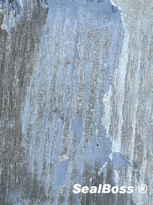
Cracking does not always affect structural performance, but it can adversely affect the durability of structures.
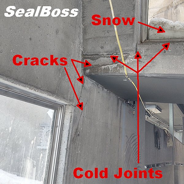
Common causes of concrete cracking are post cure and drying shrinkage, thermal stress, chemical reaction caused by alkali-reactive silica & sulfates, freezing and thaw cycles due to water expansion, corrosion of steel rebar, settlement, load stresses, construction short comings such as design and construction errors.
The incorporation of steel reinforcement within structural concrete allows these elements to function under both compression and tension, frequently resulting in tension-induced fracturing of the concrete in certain regions.
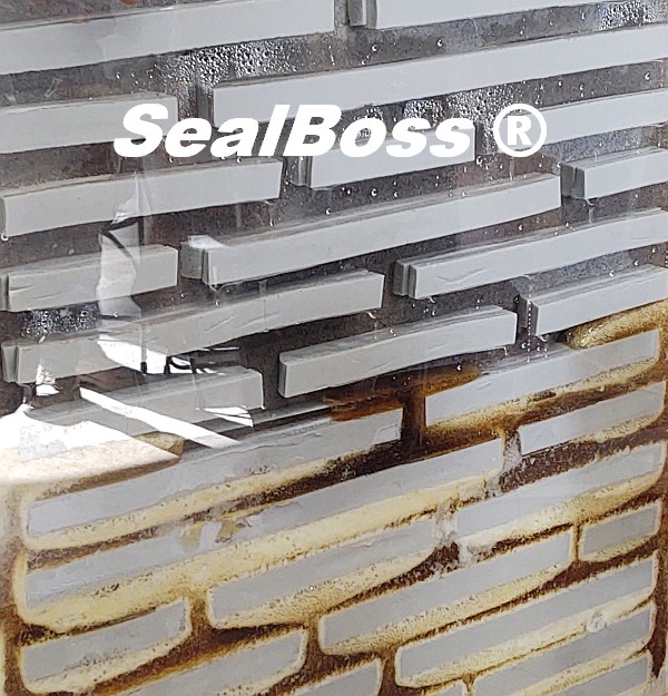
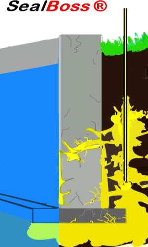
Water is a major contributor to concrete corrosion in parking garages, bridges, industrial facilities and more. Water, chloride and carbon dioxide can migrate deep into the structure initiating corrosion of the reinforcement structure.
Water ingress, facilitated by fissures or compromised joints, often carries corrosive substances and chlorides that contribute to the degradation of concrete and the corrosion of steel reinforcements and rebar. Fortunately, epoxy concrete crack injection can address many of these concerns in structures exhibiting signs of such issues. Employing a proficient concrete repair team can frequently circumvent the need for a complete teardown.
SealBoss Epoxy Resins
SealBoss Epoxy Crack Injection resins for structural crack repairs conform to ASTM C881 specifications, with appropriate viscosities for the crack widths. The bond strength of epoxy to clean concrete is greater than the tensile strength of concrete itself.
Wider cracks may require a higher viscosity epoxy, small cracks a lower viscosity injection resin. Depending on the requirements, viscosities may range from approximately 150 to 600 cps at room temperature.
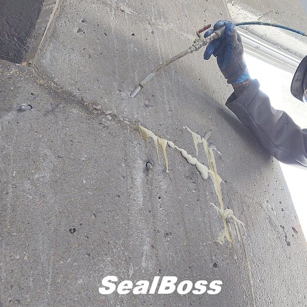
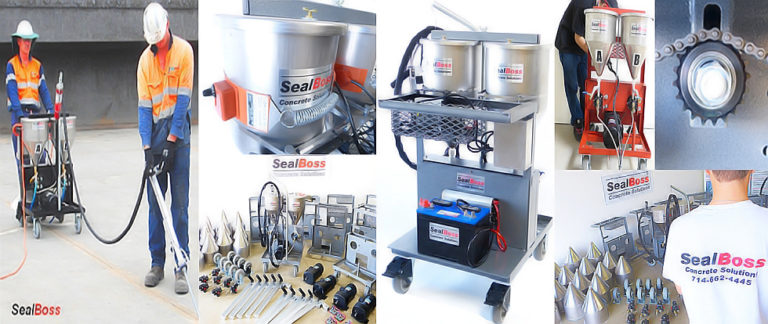
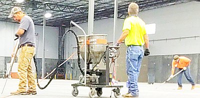
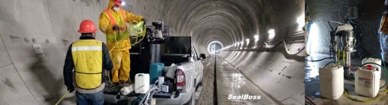
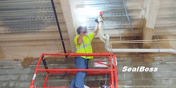
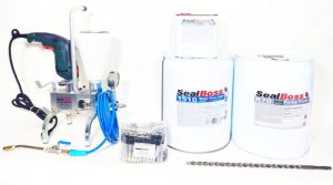
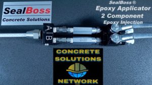
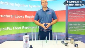
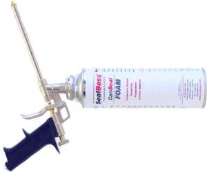
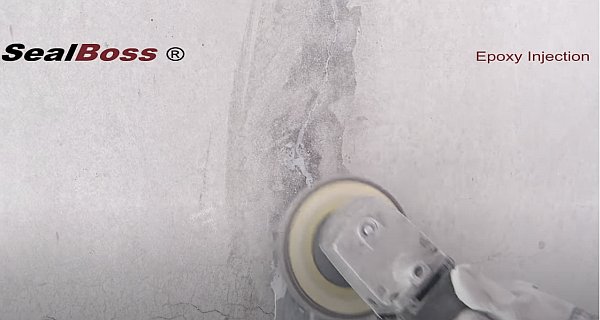
SealBoss Epoxy Crack Injection concrete repair can be performed with SealBoss Epoxy Cartridge Systems or SealBoss epoxy bulk resins using air guns, hand-actuated delivery systems, or dual-component injection electric or air-driven pumps.
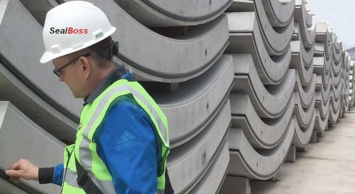
Prior to repair, the structure must be carefully examined to establish that epoxy crack injection is indeed the correct method to regain the desired structural integrity. The cause of cracking must be determined. Cracks must be identified and the allowable crack width needs to be established. The width of cracks can be measured by using crack gauge cards. In some instances it may be recommended to measure the expansion and contraction cycles of a crack. To determine the depth and cause of cracking, core samples can be taken and examined by petrographic and chemical testing. In addition, nondestructive testing (NDT) ultrasonic pulse velocity can be used to measure the depth of cracks.
Once it has been established that epoxy concrete crack injection is the chosen method of repair, the SealBoss Epoxy Injection System can be utilized to restore the structural integrity of the concrete.
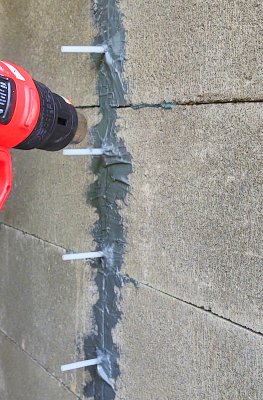
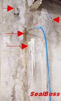
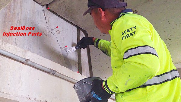
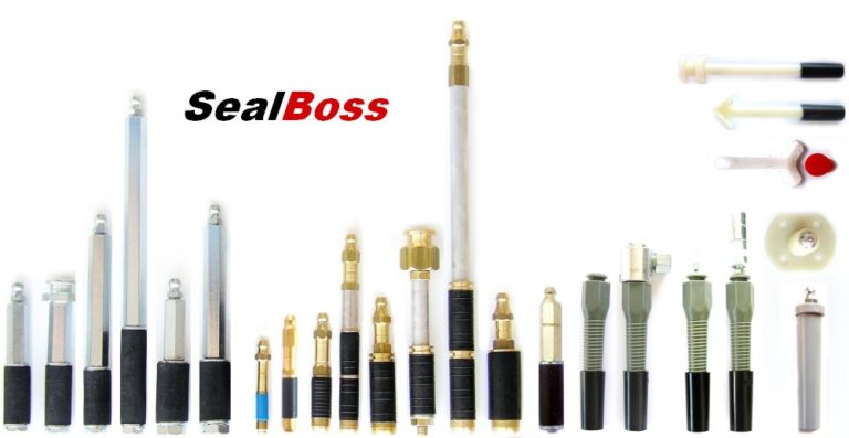
SealBoss ® Surface Mount Injection Ports
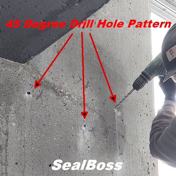
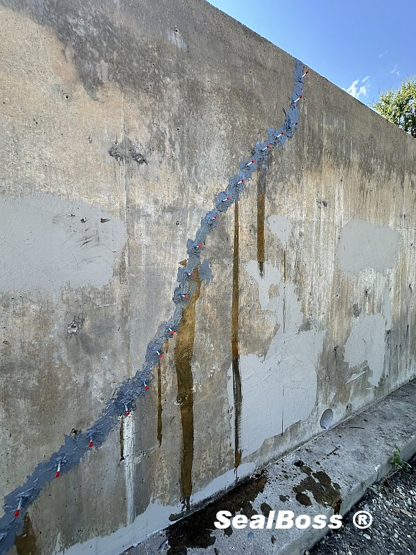
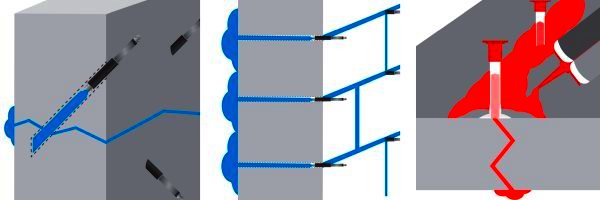
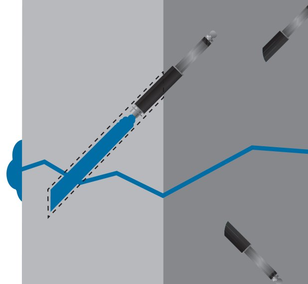
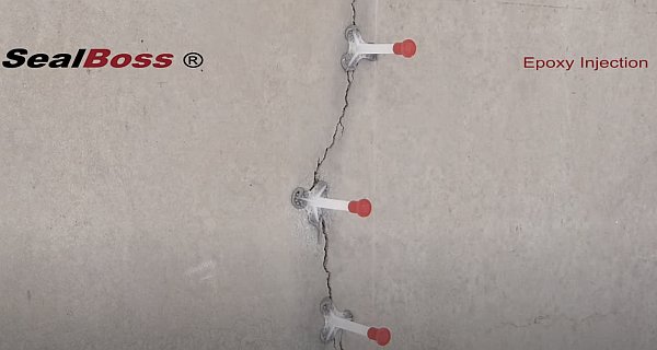
Surface-mounted injection ports are typically adequate for injecting most cracks. However, badly deteriorated concrete or higher injection pressures may require the use of drill-in or hammer-in plastic ports or even mechanical packers. Surface ports, aka plastic tubing ports, are glued on the surface over the open cracks using SealBoss epoxy paste adhesive. The injection ports are typically installed at a spacing that is equal to or slightly narrower than the depth of the crack. Hairline cracks require closer spacing than wider cracks.
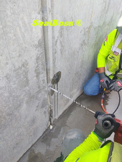
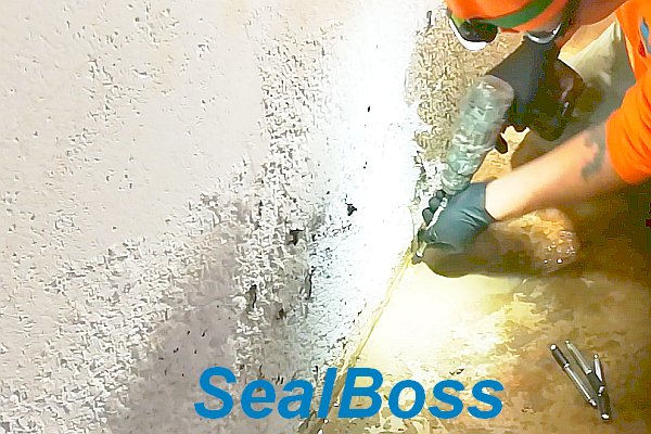
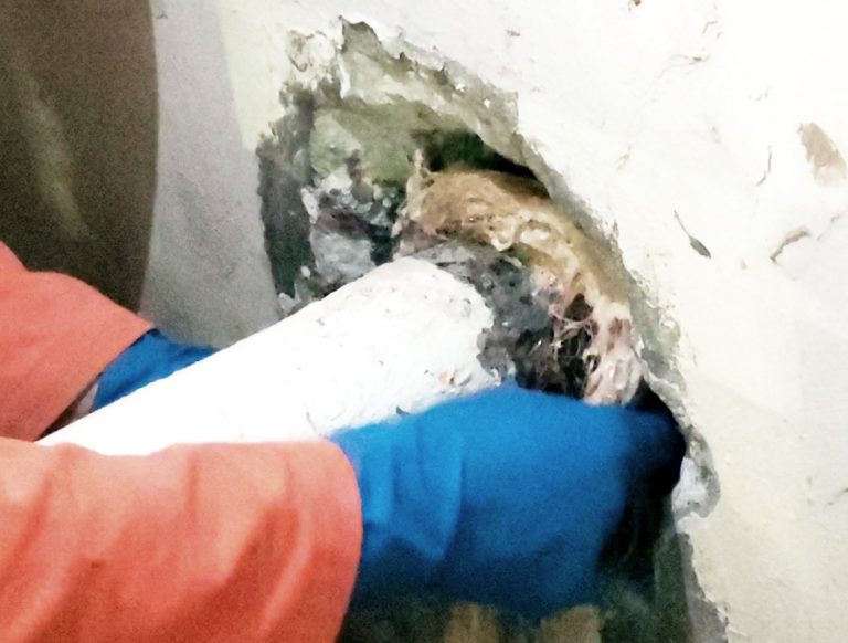
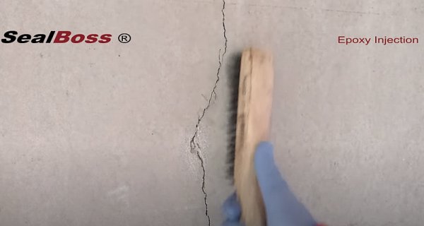
Wire brushing and vacuuming the crack surface along the crack is often sufficient for surface preparation. In areas of badly deteriorated concrete, pressure washing, grinding, and V-grooving may be specified.
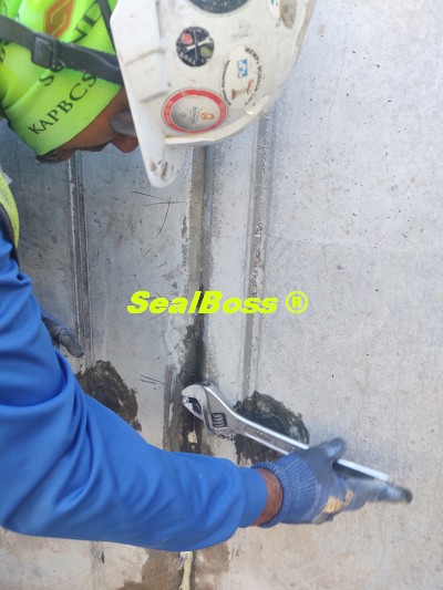
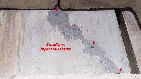
After the surface has been cleaned, surface ports are installed. Sealboss 4500 crack-sealer epoxy paste will be used as surface port adhesive and be applied on the face of the crack between and around the ports.
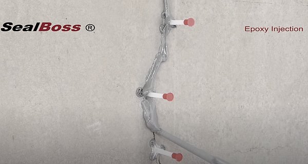
Once the injection ports are installed, Sealboss 4500 crack-sealer epoxy paste is applied on the face of the crack between and around the ports. To contain the epoxy resin in the crack until it hardens, it is a good practice to seal cracks on all sides of the substrate if possible.
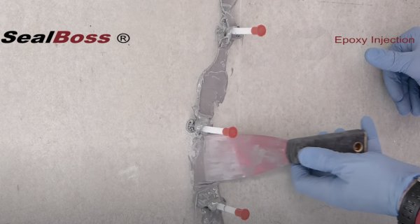
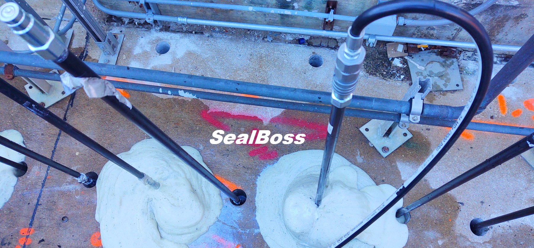
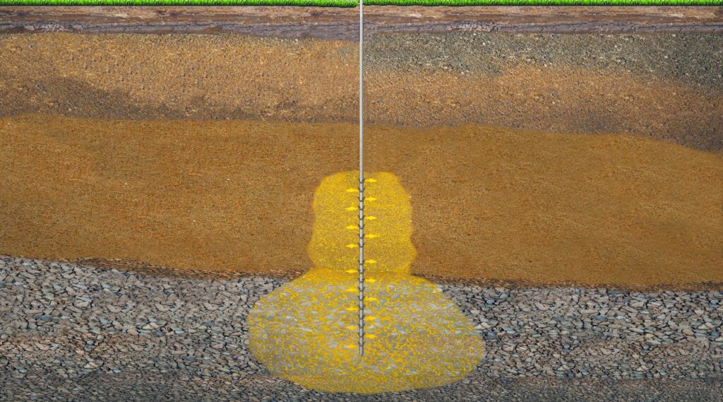
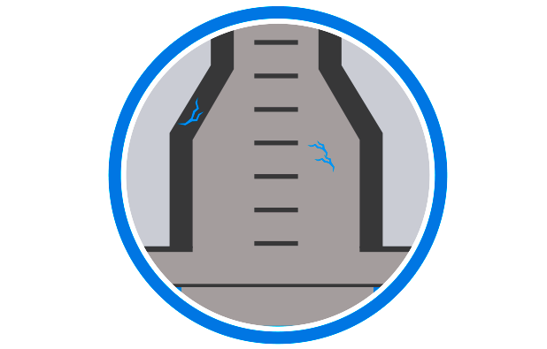
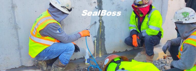
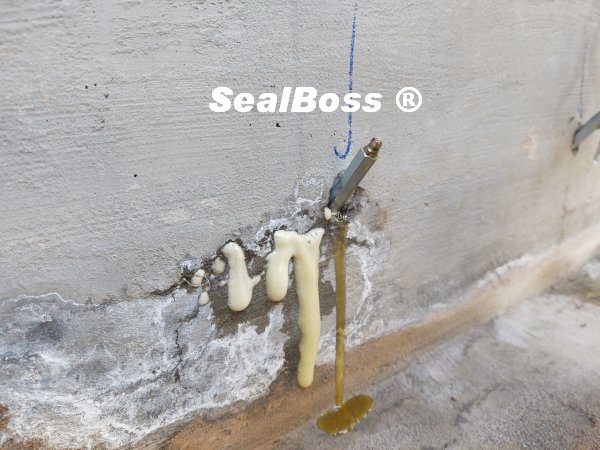
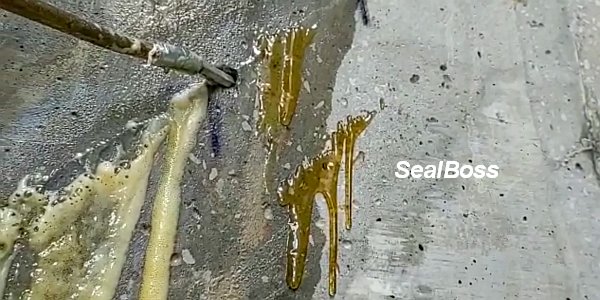
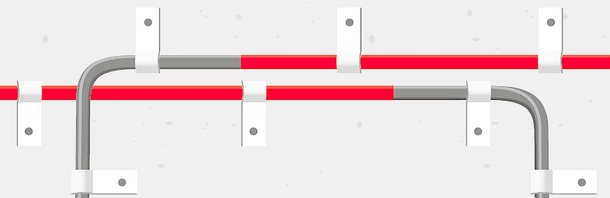
Begin the Epoxy Crack Injection at the Point of the Structure
As soon as the epoxy appears at the next higher port, the current port is capped and the injection is continued from the next port. Multi port injection may be used in most epoxy injection environments. Typical injection pressures are between 50 to 100 psi (3 to 6 bars), with very fine cracks requiring pressures of over 200 psi (12 bars).
Epoxy resins are temperature sensitive. At higher temperatures resin viscosity decreases, but reaction time increases. For best performance during application, it is advised to keep the resin at room temperature or slightly above during injection.
After the injection resin has cured, the epoxy paste adhesive is removed from the surface of the concrete.
Quality assurance and control measures include visual observation of the injection process and product consumption, testing the injection equipment for mix ratio, taking core samples and testing repaired cracks using nondestructive testing methods.

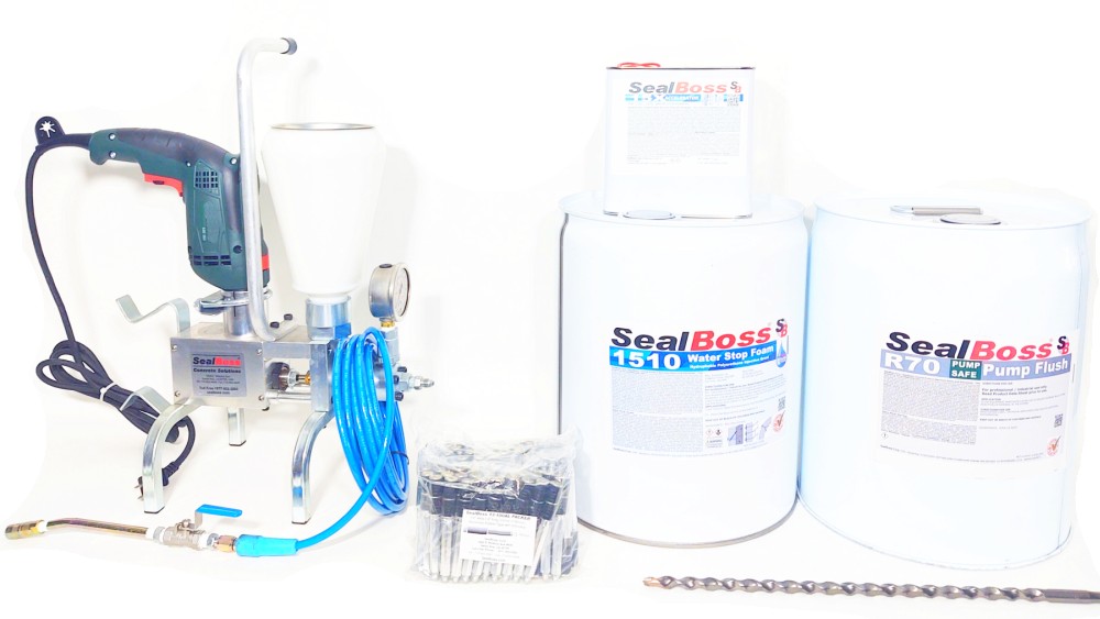
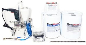
Epoxy Crack Injection System – Epoxy Resins, Ports, Pumps
SealBoss epoxy injection system solution.
Ranging from epoxy resins and structural epoxy gels to injection ports and two component epoxy pumps.
SealBoss Highest Quality Epoxy Standard
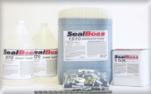
Injection Epoxy Resin
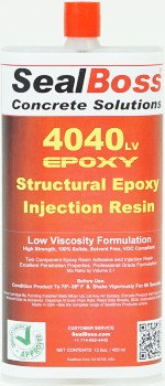
Multi-Use Epoxy Resin
4040 low viscosity, 100% solids, hi-mod, 2-component, moisture-tolerant, low-viscosity, high strength, multi purpose, epoxy injection resin adhesive
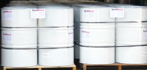
– Commercial Bulk Packaging
– Cartridge System
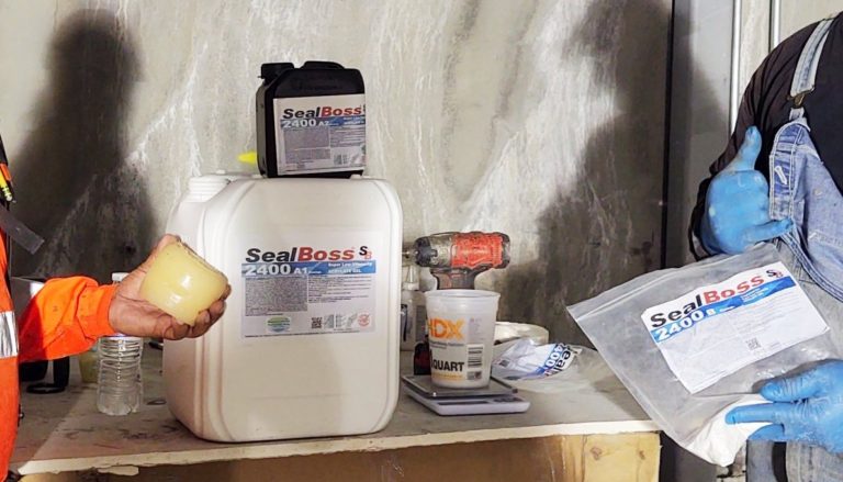
Super Low Viscosity Epoxy Resin
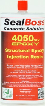
4050 super low viscosity, 100% solids, hi-mod,
2-component, moisture-tolerant, low-viscosity, high strength, epoxy injection resin adhesive
– Commercial Bulk Packaging
– Cartridge System
SealBoss Highest Quality Epoxy Standard
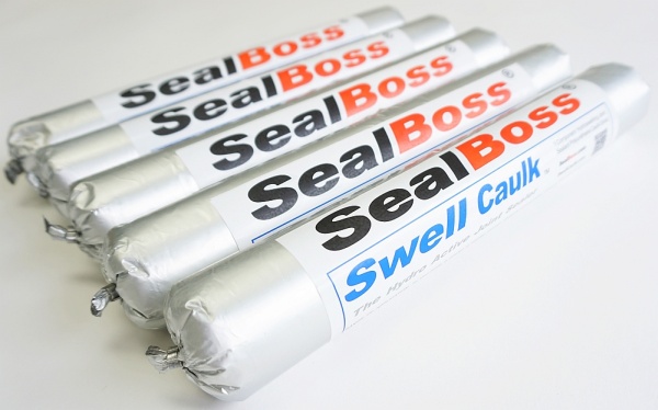
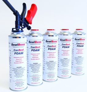
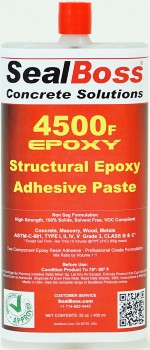
Fast Cure Epoxy Paste
Epoxy paste products for surface repairs, to prepare cracks for resin injection, and to bond SealBoss surface ports. 4500 NSF Drinking Water Approved Formula available.
– Commercial Bulk Packaging
– Cartridge System
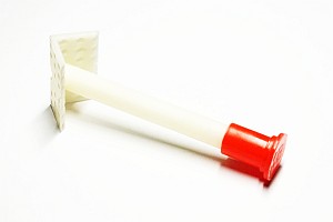
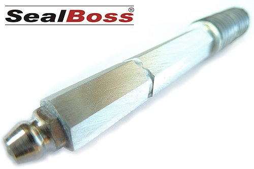
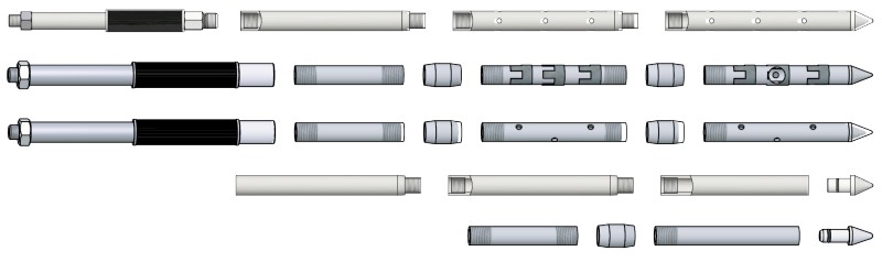
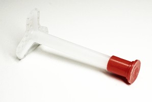
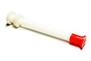
Epoxy Injection Port – Industry Standard Bestseller
Durable plastic design surface mounted port suitable for epoxy injections. Tri-Base design with perforation holes for best possible adhesion with SealBoss 4500 Epoxy Paste Adhesive. Caps included. For EP grouts.
Bestseller – a SealBoss Standard
Epoxy Injection Drill Hole Mount Port
Durable plastic port designed to fit 1/2″ drill hole for higher injection pressures than regular surface ports. Suitable for epoxy injections. Caps included. For EP grouts.
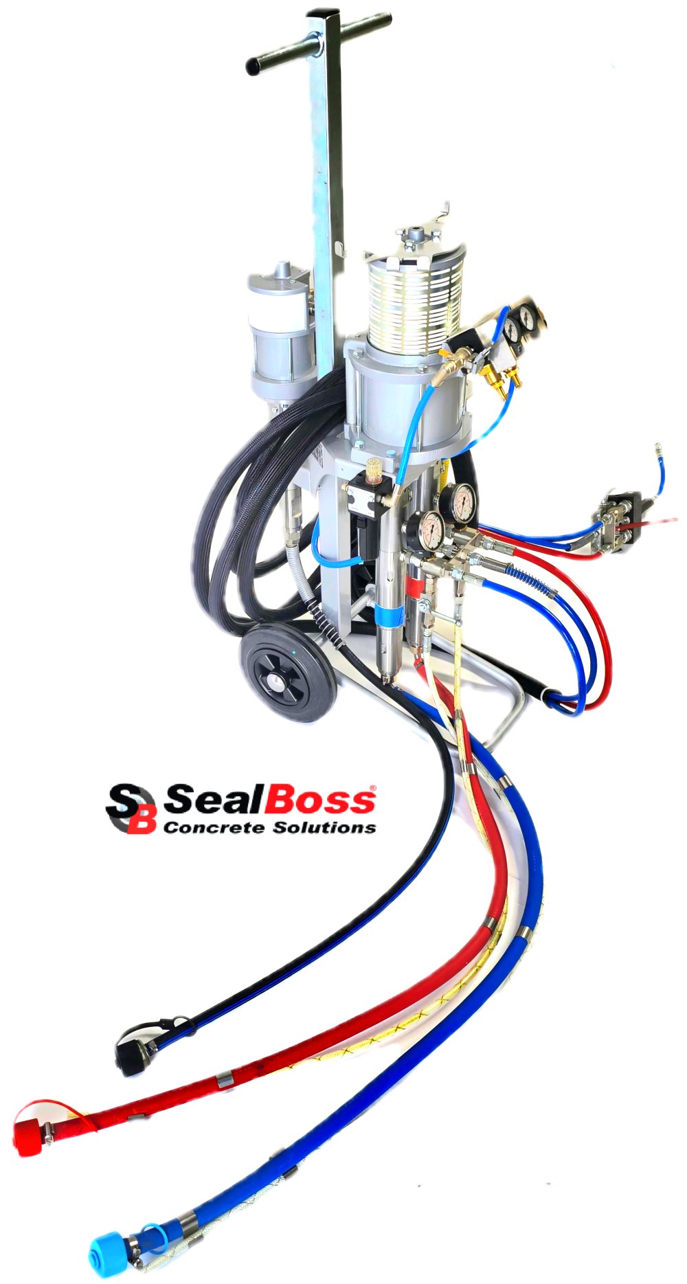
High & Low Pressure
Epoxy Injection & Polyurethane Injection
- Top of the Line – Professional Use
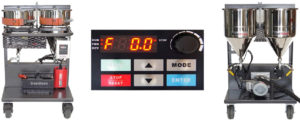
- Pumps Epoxy & PU resin
- Pneumatic
- 850 psi
- 2 Comp.
- Ratio: 2:1 Standard, 1:1 custom
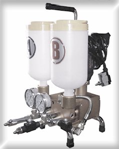
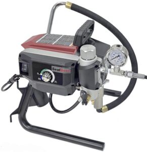
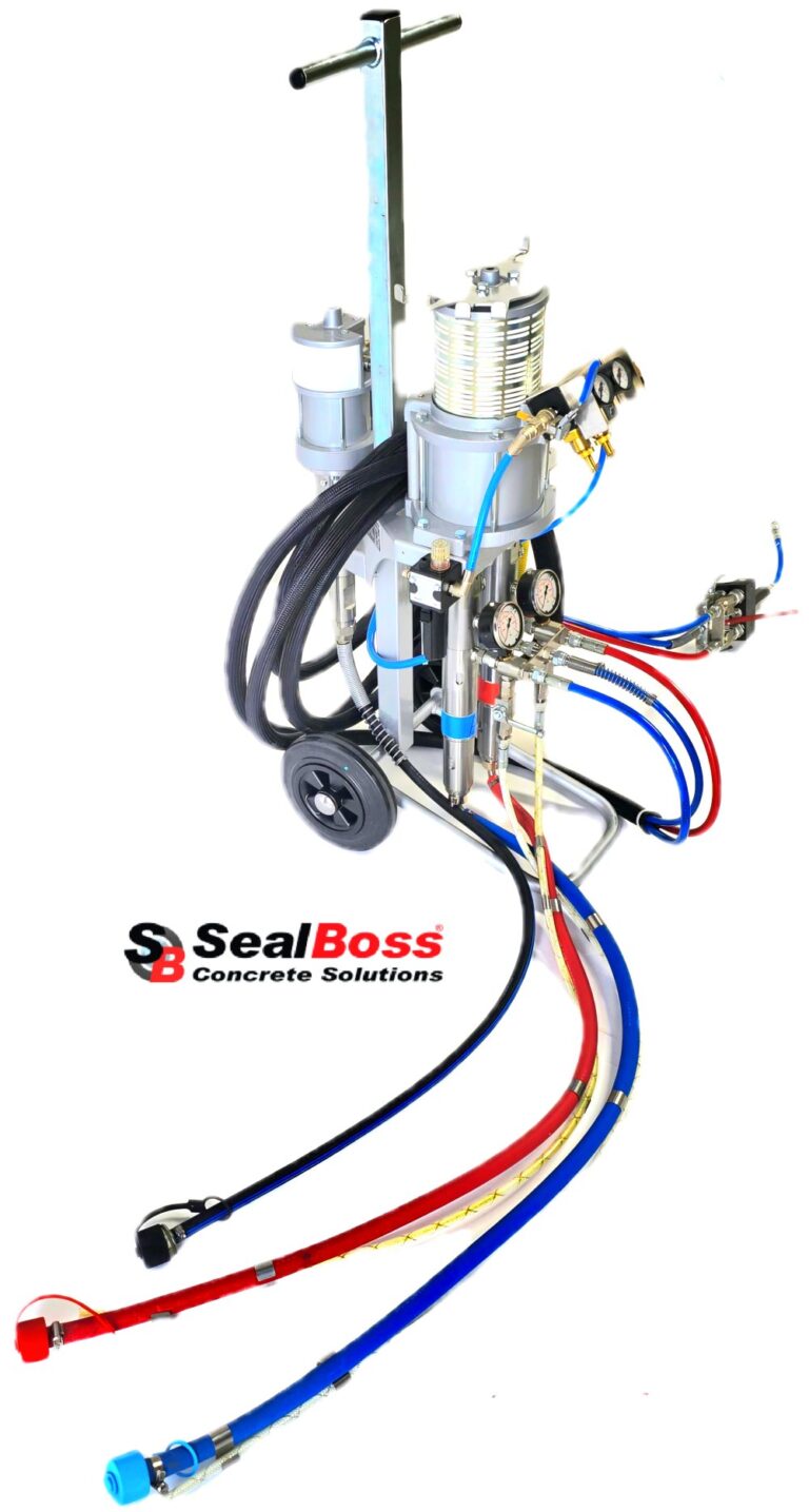
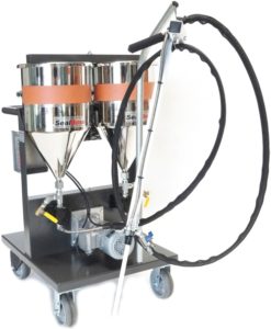
High & Low Pressure
Epoxy & Polyurethane Injection Piston System
- Versatile,
- Pumps Epoxy & PU Resin
- Electric Drill Operated
- Dual Piston System
- 5000 psi
- 2 Comp.
- Ratio: 2:1 standard, 1:1 custom