





Concrete Injection as a Complete System: Matching Material, Pump, Packers, and Method
The injection material cannot be selected responsibly without considering how it will be prepared, delivered, connected, controlled, cleaned, and documented.
SealBoss Corp. • Technical blog series • Technical review required before publication
Scope boundary
This part explains system interfaces and readiness. It does not replace current product data sheets, SDS documents, application guidelines, packer information, or pump manuals. Field documentation is addressed in Part 4.
On this page
- The material does not reach the structure by itself
- Begin with the repair objective and exact product variation
- Pump selection is part of material selection
- Pressure and flow describe different parts of the injection
- Packers or ports are the interface with the structure
- Hoses, valves, couplers, mixers, and applicators complete the delivery path
- Scan before drilling and define the intended pathway
- Safety and compliance belong in the readiness review
- Cleaning and shutdown must be planned before injection starts
- Field context: one documented system, not a universal specification
- Training makes concealed behavior easier to understand
- Complete-system readiness review
The material does not reach the structure by itself
Concrete injection is sometimes discussed as if the resin performs the repair alone.
In practice, the material must move through a coordinated delivery system. It may need to be proportioned, mixed, accelerated, pumped, carried through hoses and valves, connected to a packer or port, introduced into a concealed pathway, observed during travel, and managed during interruption, shutdown, and cleaning.
Each component affects the others.
The material, pump, packer or port, coupler, hose, applicator, cleaner, preparation method, operator, training, and current technical documents should therefore be reviewed as one system.
Complete-system map
- Repair objective and site condition define what the system must do.
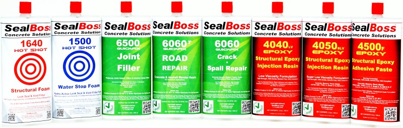
- Material family and exact product variation define preparation, reaction or cure behavior, viscosity, mixing, and cleaning requirements.
- Pump configuration defines ratio capability, pressure, output, power source, and material-contact components.
- Hoses, valves, mixers, couplers, and applicators carry and control the material.
- Packers or ports connect the delivery system to the structure.
- Preparation and drilling controls establish the intended pathway and protect embedded components.
- Cleaning, shutdown, safety, documentation, and training keep the system operable and traceable.
Begin with the repair objective and exact product variation
Water-control injection, structural epoxy crack repair, joint treatment, penetration sealing, void filling, and curtain injection involve different material behaviors and delivery requirements. Active water, damp or dry conditions, movement, defect geometry, expected volume, access, substrate and ambient temperature, and service environment may further affect the configuration.
The objective should be stated before the equipment list is prepared. That statement gives the contractor and technical representative a basis for reviewing material family, component configuration, viscosity, reaction or cure profile, required flow, pump category, injection-point type, connection method, and cleaning procedure.
Temperature deserves specific attention. Material temperature, substrate temperature, and ambient temperature may affect viscosity, reaction or cure speed, pot life, pressure response, and pump behavior. Exact limits and conditioning requirements must come from the current data sheet, application guideline, and equipment manual.
Without that sequence, the crew may arrive with components that are individually useful but not coordinated for the intended application.
Pump selection is part of material selection
A pump should not be selected only because it can generate pressure.
Injection performance depends on the relationship among component ratio, material viscosity, output volume, pressure, hose arrangement, seal and wetted-part compatibility, injection-point resistance, defect geometry, and the volume that must be delivered.
When comparing pumps, review at least these specification categories:
| Pump specification | Why it matters | Controlling source |
|---|---|---|
| Component configuration and ratio | Determines whether one or more material streams can be prepared and proportioned correctly. | Exact product data sheet and pump manual |
| Maximum pressure | Defines equipment capability, not the pressure that should be used on a particular structure. | Pump manual and application guideline |
| Output volume or flow range | Affects delivery for fine cracks, defined joints, higher-volume voids, or broad-area work. | Pump manual |
| Power source | Electric, pneumatic, hydraulic, or manual operation affects site logistics and controls. | Pump page and manual |
| Material-contact components and seals | Compatibility affects operation, cleaning, and maintenance. | Pump manual and written technical confirmation |
| Hose and applicator arrangement | Determines how material reaches the packer or port and how components are mixed where applicable. | Pump manual and system documentation |
| Cleaning and shutdown requirements | Must be planned before material enters the equipment. | Current cleaning guidance, SDS, and pump manual |
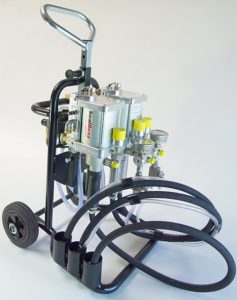
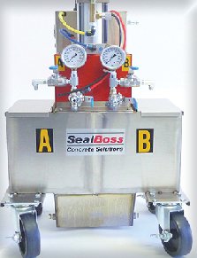
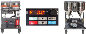
The SealBoss Pumps Overview, Leak-Seal and Crack-Injection Pumps, and Epoxy Injection Pumps pages organize the current equipment paths by application and material configuration. Model names, ratios, maximum pressure, output, material-contact components, current availability, and product-pump compatibility must be confirmed from the current product page and pump manual.
The existence of several pump platforms does not create a universal model-selection chart. It shows why the exact product and application must be matched to the current equipment documentation.
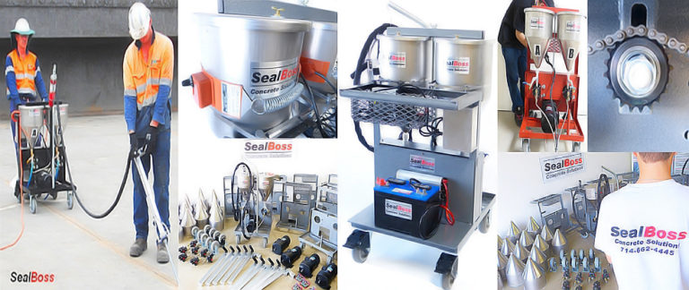
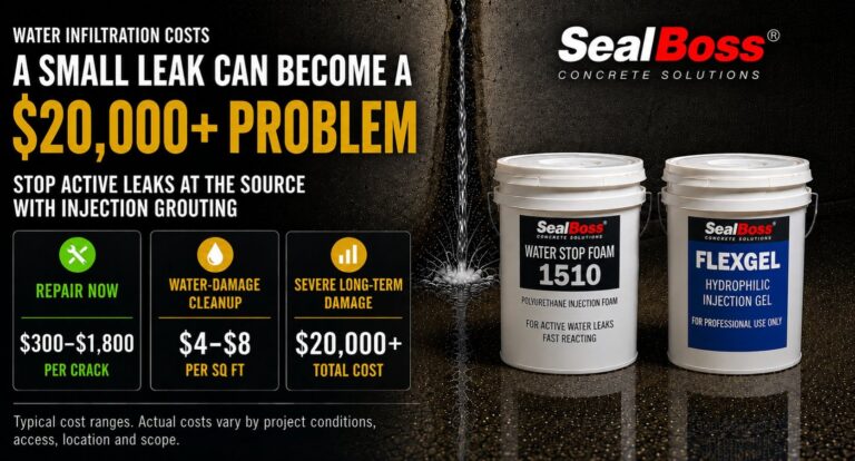
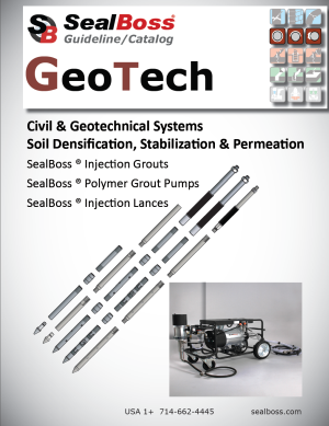
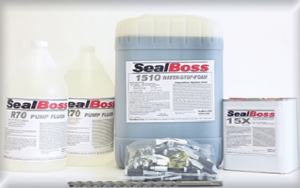
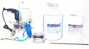
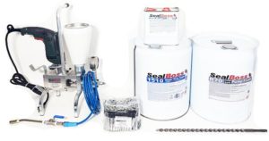
A coordinated product, pump, and packer system
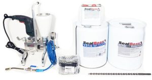
The image provides a practical system overview. Exact product-pump compatibility and operating requirements remain controlled by the current data sheet, application guideline, and equipment manual.
Pressure and flow describe different parts of the injection
Pressure is often emphasized because it can be observed on a gauge. It does not, by itself, describe material travel or repair completeness.
The reading may be influenced by material viscosity, temperature, hose length, valve restriction, pump configuration, packer condition, crack geometry, concrete density, blockage, elevation, reaction, and resistance within the treatment path.
Flow, material consumption, visible returns, leakage at the surface, and changes in water discharge provide additional information. None should be interpreted in isolation.
A rising pressure does not automatically prove that a crack is filled. Material appearing at an adjacent point may show communication between two locations, but it does not reveal every branch or void. A reduction in water flow indicates a change in the active pathway; it does not establish that every connected path has been addressed.
Review Crack Injection Pressure for the broader explanation, then follow the current application guideline and pump manual for the exact system.
Packers or ports are the interface with the structure
The packer or port connects the delivery equipment to the repair pathway.
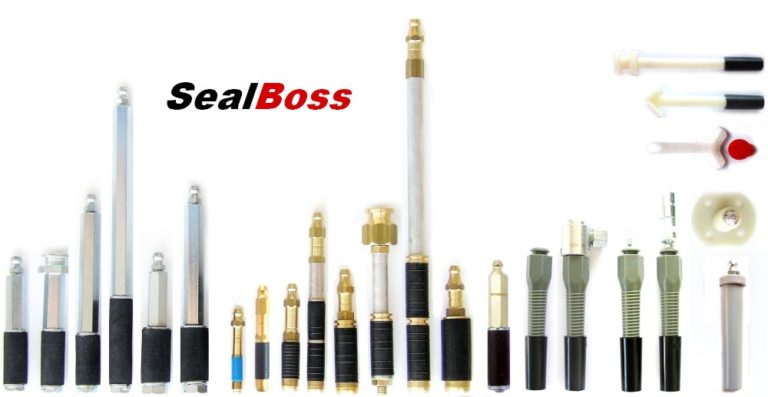
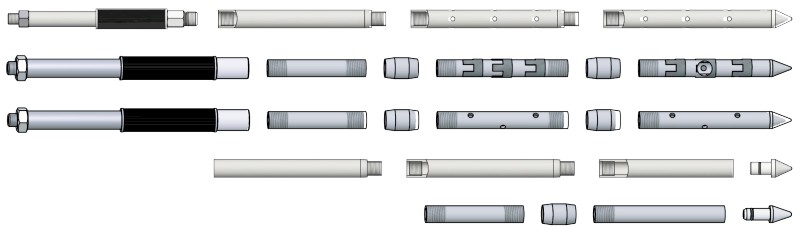
SealBoss provides mechanical packers, hammer-in ports, surface-mounted ports, epoxy ports, button-head configurations, Zerk fittings, couplers, needles, and injection lances. The current Injection Packers, Ports, and Couplers page and Packer Overview should be used to verify exact dimensions and connections.
A useful packer comparison starts with the categories below. Values are intentionally omitted from this article because they must be taken from the current product source.
| Selection field | What the reader should verify |
|---|---|
| Packer or port type | Mechanical, hammer-in, surface-mounted, epoxy port, needle, lance, or other approved category |
| Diameter | Exact outside diameter and compatible drilled opening |
| Drill-bit size | Current requirement for the selected packer and substrate condition |
| Length | Reach, anchorage, wall geometry, and access |
| Body material | Steel, brass, aluminum, zinc, plastic, or another listed material |
| Head type | Zerk, button-head, or other connection |
| Coupler and hose interface | Secure match to the delivery system |
| Check-valve or anti-return arrangement | Current product configuration and intended control |
| Removal or finishing requirement | Project and application-specific closeout |
A packer should not be treated as a minor consumable chosen after the pump arrives. It determines how the equipment connects to the structure and how material delivery is controlled at the injection point.
Go deeper: Review Injection Packers, Ports, and Couplers, Injection Needles, Injection Lances, and Hoses, Applicators, Accessories, and Parts.
Mechanical packers and surface ports
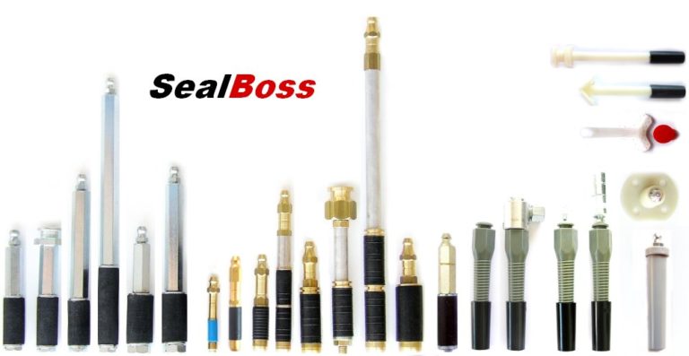
The current SealBoss Packer Overview and individual product pages should be used to confirm dimensions, connection type, and application limitations.
Hoses, valves, couplers, mixers, and applicators complete the delivery path
The components between the pump and the packer or port are part of the operating system.
The hose must suit the equipment, material, connection arrangement, and intended operating conditions. Valves and control devices must be compatible with the selected material and pump. The coupler must attach securely to the injection point. Static mixers, anti-return arrangements, applicators, extensions, and other components may be required for particular multicomponent or access conditions.
Every added connection introduces another point that must be inspected, assembled, operated, depressurized, and maintained under the approved procedure.
A coupler that does not match the head can stop production or lead to improvised adapters. An unsuitable hose or valve may create unnecessary restriction. A damaged seal can allow leakage. A worn connection may make it difficult to control disconnection and movement between points.
Review the entire delivery path before the material enters the pump.
Scan before drilling and define the intended pathway
Even a compatible material and equipment package cannot compensate for an undefined target.
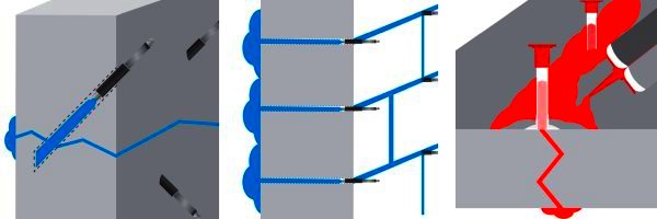
The crew should understand what each point is intended to reach, how the area will be prepared, how embedded components will be avoided, how uncontrolled discharge will be contained, and how the sequence relates to defect geometry.
Available drawings and construction records should be reviewed first. Where the risk and project conditions justify it, ground-penetrating radar, electromagnetic or magnetic rebar locators, cover meters, or other non-destructive evaluation methods may help identify reinforcement, conduits, post-tensioning components, and embedded objects before drilling. FHWA guidance on ground-penetrating radar describes its use for mapping reinforcement and other subsurface features; ACI PRC-228.2-13 provides broader industry context for non-destructive test methods.
These tools have limitations. Scanning should be planned and interpreted by qualified personnel, and it does not replace drawings, utility-location procedures, or project-specific restrictions.
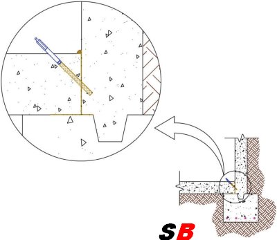
Detailed drill angle, depth, spacing, and preparation must come from the current SealBoss application guideline or approved project method statement.
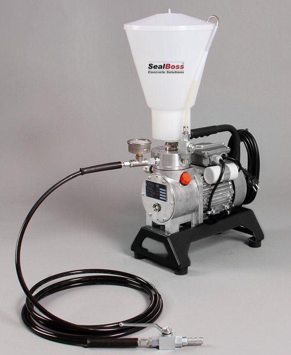
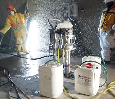
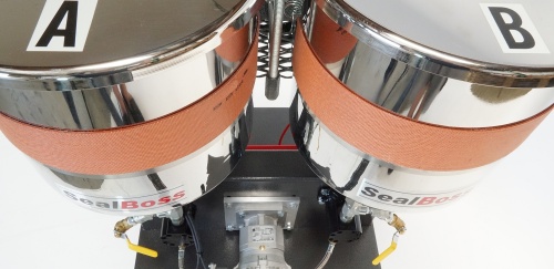
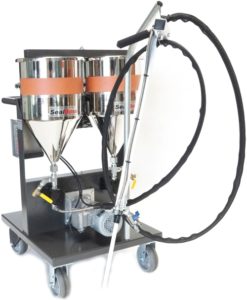
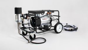
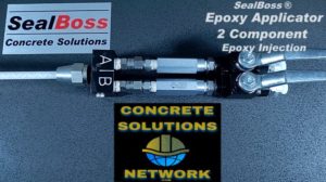
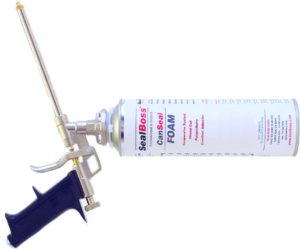
Delivery components for plural-component systems
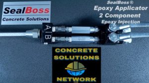
This equipment image is used in place of an unapproved drilling diagram. Drilling angle, offset, depth, and spacing must be taken from the current application guideline rather than inferred from a generic illustration.
Safety and compliance belong in the readiness review
System readiness includes the work environment, not only the equipment cart.
Concrete drilling may generate respirable crystalline silica. OSHA 29 CFR 1926.1153 includes Table 1 controls for specified equipment and tasks, including handheld and stand-mounted drills. Employers must determine the applicable controls, exposure assessment, respiratory protection, housekeeping, training, and written-plan requirements for their work.
Injection may also occur in pits, tanks, vaults, manholes, and similar spaces. OSHA 29 CFR 1926 Subpart AA addresses confined spaces in construction. Tunneling work may instead fall under 29 CFR 1926 Subpart S, and the regulatory scope should be evaluated by the employer and responsible safety personnel.
Product hazards, handling, exposure controls, and personal protective equipment must come from the current SDS and approved safety documentation. This article does not replace a site-specific safety plan or regulatory assessment.
Cleaning and shutdown must be planned before injection starts
Reactive, curing, or adhesive materials may remain in pumps, hoses, mixers, valves, applicators, and couplers after use.
The required cleaner, conditioner, water flush, solvent, timing, disassembly, storage, waste handling, and restart procedure depend on the exact product and equipment configuration. Those instructions must come from the current product information, SDS where applicable, SealBoss cleaning guidance, and pump manual.
The SealBoss Resource Page links to pump information, SDS documents, technical documents, and SealBoss R70 Pump Flush. The crew should review cleaning before material enters the system and have the required materials, collection containers, tools, and replacement components at the work area.
A system that can be started but cannot be cleaned correctly is not ready for professional operation.
Field context: one documented system, not a universal specification
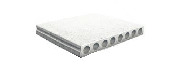
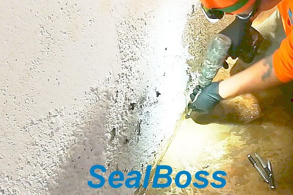
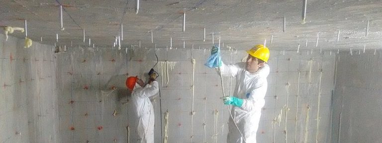
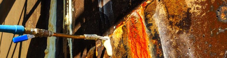
The Hollow-Core Concrete Slab Water Leak Repair case study identifies SealBoss 1510 Water Stop Foam with accelerator, SealBoss aluminum mechanical packers, a SealBoss P2002 single-component injection pump, SealBoss R70 Pump Flush, and supporting drilling and inspection equipment.
The project demonstrates a complete-system sequence:
- The condition and concealed cells were investigated.
- The treatment area and water-control objective were defined.
- A named material and accelerator were documented.
- A pump and packer system were identified.
- Cleaning materials and supporting tools were planned.
- The work and follow-up recommendations were recorded.
The case study is not a universal specification. Current data sheets, packer information, manuals, guidelines, and project conditions must control any future selection.
Training makes concealed behavior easier to understand
Injection work involves material movement that is difficult to understand from product descriptions alone.
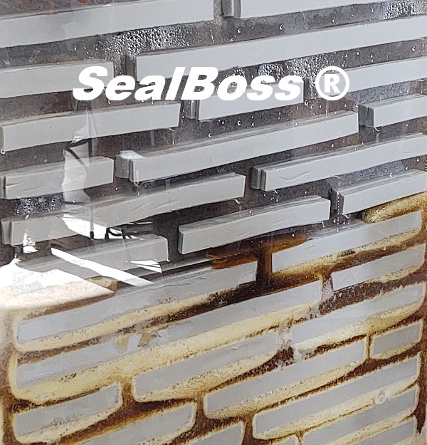
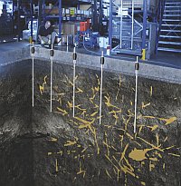
Hands-on training can allow contractors to observe drilling, packer placement, material preparation, pump operation, material travel, reaction behavior, connection changes, cleaning, and shutdown. Cut-away or transparent demonstrations can make otherwise concealed movement visible and help crews understand why similar gauge readings or returns may have different meanings under different conditions.
Review SealBoss Training and Certification for current program information. Training supports the technical documents; it does not replace them.
Complete-system readiness review
Before mobilization, confirm that:
- The repair objective and treatment area are documented.
- The exact material and variation are identified from current sources.
- The pump is appropriate for the component configuration, ratio, pressure capability, output, seals, hoses, and cleaning requirements.
- The packer or port, drill-bit requirement, head type, coupler, hose, and applicator are coordinated.
- Embedded-component scanning and drilling restrictions have been addressed.
- Substrate, material, and ambient temperatures are within the controlling documents.
- Current data sheets, SDS documents, application guidelines, and pump manuals are available.
- Cleaning, shutdown, waste, silica, confined-space, and site-safety requirements have been planned.
- Operators understand the method and know when technical support is required.
This review is the point at which separate products and equipment become a workable injection system.
Related articles, products, equipment, and technical resources
Use the links below to move from the educational framework to the relevant SealBoss application, product, equipment, case-study, or technical page.
Leak-Seal and Crack-Injection Pumps
Pump pathways for water-stop and crack-injection work.
Injection Packers, Ports, and Couplers
Mechanical packers, ports, connections, and accessories.
Hoses, Applicators, Accessories, and Parts
Complete the delivery path from pump to injection point.
Frequently asked questions
Maximum pump pressure is an equipment capability. Appropriate field pressure depends on the exact material, pump, structure, pathway, packer or port, application guideline, and observed response.
Review component ratio, maximum pressure, output volume or flow, power source, material-contact components, seal compatibility, hose and applicator arrangement, and cleaning requirements.
The team should verify packer or port type, diameter, drill-bit size, length, body material, head type, coupler, check-valve arrangement, substrate condition, access, and current application guidance.
Reactive or curing materials can remain in equipment and hoses. The correct cleaner, timing, disassembly, shutdown, and restart procedure depend on the exact material and pump system.
Confirm the system, then establish the field record and verification plan before mobilization.
Current SealBoss technical documents remain controlling. Contact a qualified SealBoss technical representative when material, equipment, or application selection requires additional review.
Technical source direction: SealBoss sources control SealBoss product and equipment facts. ASTM, ICRI, ACI, OSHA, and other primary authorities provide independent industry or regulatory context within their stated scopes. Project-specific suitability, engineering decisions, warranties, and field procedures require the current controlling documents and authorized responsible parties.