Search

news | blog

Joint Filler Maintenance – Elongation, Separation, Repair

Technical Bulletin

Joint Filler Maintenance
Elongation - Separation - Repair

A Concise Guide for Ensuring Optimal Performance and Longevity of Your SealBoss Joint Filler

Safeguarding the Durability of Your Concrete Joints

Background

The tensile elongation of semi-rigid joint fillers is a common characteristic to consider. Ultimate tensile elongation pertains to the degree of expansion a material can undergo, in terms of its length, before succumbing to fracture under tensile force. It is a common misconception, that employing a joint filler with a high elongation value can facilitate early joint filling in new flooring, with the filler then able to ‘stretch’ in accordance with the joint as it expands due to slab shrinkage.

This reasoning is flawed.

Tensile testing gauges the capacity of the joint filler material to stretch along the test specimen’s length. However, control joints in concrete floors don’t lengthen but rather widen laterally — side-to-side . Thus, the tensile elongation test does not accurately simulate real control joint movement or the joint filler’s capacity to accommodate this movement.

Consider the polyurea joint filler with a tensile elongation of 200%. It can stretch laterally — side-to-side — approximately 10% before it starts to split either cohesively (within the filler itself) or adhesively (along the joint filler/concrete bond line). Given that the shrinkage-induced joint widening often surpasses what the joint filler physically can withstand even under the best circumstances, early installation of joint fillers will likely lead to splitting or a loss of adhesion. Concrete shrinkage can cause the Joint Filler to split or separate over time.

This is a normal occurrence and not an indication of joint filler failure, and is clearly stated by the American Concrete Institute in the ACI 302.1R-04 Guide for Concrete Floor and Slab Construction, Section 9.10 – Joint Filling and Sealing  

” 9.10.1  Time of filling and sealing—Concrete slabs-on-ground continue to shrink for years; most shrinkage takes
place within the first 4 years. The most significant shrinkage takes place within the first year, especially the first 60 to 90 days. It is advisable to defer joint filling and sealing as long as possible to minimize the effects of shrinkage-related joint opening on the filler or sealant. This is especially important where semirigid fillers are used in traffic-bearing joints; such fillers have minimal extensibility. If the joint should be filled before most of the shrinkage has occurred, separation should be expected between the joint edge and the joint filler or within the joint filler itself. These slight openings can subsequently be filled with a low-viscosity filler recommended by the same manufacturer as the original filler. If construction traffic dictates that joints be filled early, provisions should be made to require that the contractor return at a preestablished date to complete the necessary work using the same manufacturer’s products. Earlier filling will result in greater separation and will lead to the need for more substantial correction; this separation does not indicate a failure of the filler. …”  (ACI 302.1R-04 – Section 9.10)

The Product

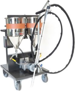
The SealBoss 6500 is a robust, semi-rigid polyurea joint filler, made entirely from solid materials. Composed of two components, it exhibits a Shore hardness of 80 A and approximately 200% elongation, indicative of its strength and flexibility. The product is primarily engineered for the purpose of filling and safeguarding contraction and construction joints found in concrete floors of industrial, retail, and commercial premises.

The formulation of SealBoss 6500 is purposefully designed to withstand the rigors of high-traffic and heavy-load environments typical of industrial and retail concrete floors. Its pivotal role is not just to withstand the continuous traffic in commercial warehouses and the load from forklift operations, but also to seal and safeguard joint edges. By doing so, it extends the longevity and maintains the integrity of the surfaces it is applied to. This makes it an indispensable solution for businesses that prioritize facility durability and maintenance.

Routine Maintenance and Cleaning

Ensure to sweep the polyurea joint filler daily to eliminate any accumulated dust or debris. For dealing with spills or hardened dirt, employ a solvent-free cleaner to dislodge the grime and proceed with your usual clean-up routine. For commercial floors that undergo auto-scrubbing, adhere to your regular cleaning protocols and perform spot cleaning as necessary.

In case the joint filler requires repair, please consider these steps:

Initiate by cleaning the area to remove any dirt and debris. Use a solvent to wipe off any residual grime, then fill the cavity with the 6500 filler. Use a floor scraper blade to remove any surplus filler, ensuring a level finish.

With a dust-free concrete saw or angle grinder equipped with a Brazed Vacuum saw blade, cut a depth of ½” (12mm) until fresh concrete is evident on both sides of the joint. Proceed to clean the filler surface by removing any dirt and debris, then wipe it with a solvent. Fill the void with polyurea joint filler and use a razor blade to shave off excess filler, resulting in a smooth finish.

Utilize a specialized removal blade, 4”, 6”, or 8”, to remove the full depth of the joint filler until fresh concrete is visible on all three sides of the joint. Once the joint is clean and free of all dust and debris, apply the new SealBoss 6500 as per the installation instructions.

Contact Your SealBoss ® Technician

Concrete Crack Injection – Polyurethane

Concrete Crack Injection Polyurethane

Concrete Crack Injection Polyurethane

Introduction:

Maintaining the design integrity of concrete structures is paramount, particularly when it comes to preventing water intrusion and ensuring long-term durability.

Leaking concrete cracks pose a significant challenge across various infrastructures, necessitating advanced and reliable repair solutions.

Concrete Crack Injection with Polyurethane (PUR) Water Stop Foam Injection is a modern and economical approach designed to effectively seal leaking concrete cracks permanently. Chosen for its efficacy and adaptability, this method addresses a wide range of issues associated with water damage, including structural erosion and the presence of efflorescence.

Highlighting the procedure and it’s benefits, this article is an introduction to leveraging PUR Water Stop Foam Injection to maintain and enhance the  integrity of concrete constructions, ensuring long-term protection against the elements.
How to Seal Leaking Concrete Cracks with PUR Water Stop Foam Injection

Zoo Exhibit Crack Repair — The Gorilla Exhibit at Omaha’s Henry Doorley Zoo was closed for renovations and repairs, including the sealing of concrete cracks that had shown signs of water intrusion, structural erosion, and visible stains from rust and efflorescence.

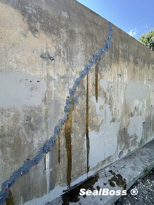
Concrete crack injection with polyurethane foam resin was the choice of repair to resolve water bearing crack leaks. Crack related damages were located at a walkway under a lofted area with multiple windows and decorative shotcrete structures where gorillas could sit and be viewed by people walking through the exhibit.

The cracks were covered in efflorescence could be seen on the walls below the lofted area as well as cracks coming off the cold joints around the precast window framing.

The crack dimensions ranged from hairline to 1/4″ joint seams with varying degrees of water intrusion and active leaks causing heavy efflorescence build up. The roof and lofted area collect and feed water during snow melt and heavy rains.

SealBoss provided an on-site technical representative to consult with the contractor on injection methods using NSF/ANSI 61 Drinking Water Contact Certified injection grout,  a high-pressure injection pump and mechanical injection packers.

Concrete Crack Injection – Polyurethane

Which products are shown in the video?

Concrete Crack Injection Polyurethane – Procedure and Repair Method

Prior to injection, the contractor had to first prep the cracks by removing any efflorescence and dirt build-up from the face of the crack using a wire brush.

Once the cracks were visible an injection plan was established to address the leaks working from the low point up.

Using the SealBoss high pressure concrete crack injection system — hydro-active, hydrophobic polyurethane foam resin, injection packers and polyurethane crack injection pump — hydro-active foam resin is injected into the cracks, expanding on contact with moisture and displacing any water in the process while creating an airtight & watertight seal.

Crack Injection Details

A – Standard Injection Procedure

One side of the lofted area had three significant cracks that resulted in substantial active leaks.  The east wall presented larger actively leaking cracks. Further, cracks and cold joints from a precast window frame created an area of leakage that needed to be injected.

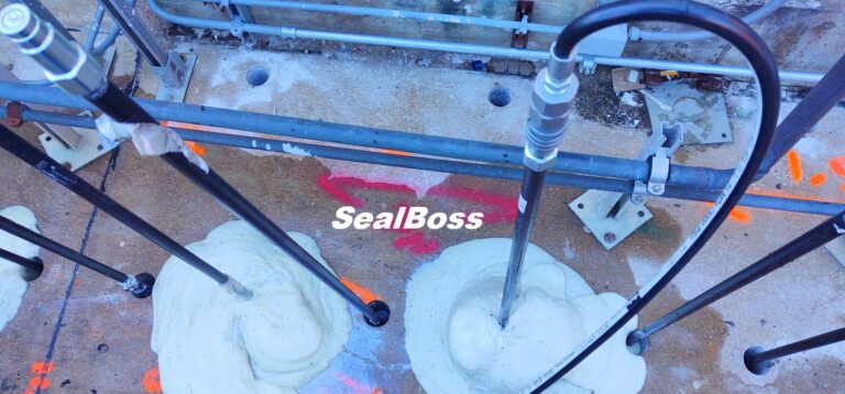
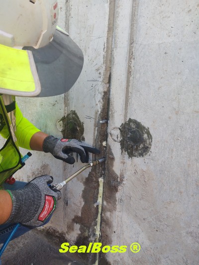
In those areas, SealBoss 1/2 inch  injection packers were placed according to SealBoss Standard Recommendations, roughly 4” from the crack in ½” holes that were drilled at a 45-degree angle back into the crack. SealBoss 1510 Water Stop Foam was injected until positive refusal of the hydro-active resin was visible from the face of the crack as well as on the exterior side of the wall when a through crack was injected.

Starting with the lowest point of the cracks, SealBoss 1510 Leak Sealing Foam Grout was injected until positive refusal was observed on the interior and exterior of the wall. Due to the temperature of the wall, around 36 degrees Fahrenheit, the contractor was advised to condition the resin to room temperature prior to use as well as adding 15% of SealBoss 1510 Accelerator/Catalyst to compensate for the cooler ambient and substrate temperature — cold temperatures slow down the chemical reaction of the injection grout.

45 Degree Angle Drilling
Concrete Crack Injection - 1 2 3 - 45 Degree Injection Technique SealBoss
1510 Foam Grout Injection

B – Custom Injection Procedure

In some areas, more complex leaking cracks and cold joints had to be sealed, requiring a deviation from standard injection packer placement.

Multiple cracks had developed connecting to a larger initial crack, creating a spider-web crack pattern. Due to the complexity of the crack system and intersections of cracks, the injection procedure was modified from the standard alternating “zipper” pattern typically recommended. Cracks were so close in proximity that packers needed to be strategically ‘custom’ placed to increase the chance for each packer drill hole to successfully intersect with the crack — resulting in a less orderly packer placement pattern.

Starting at the low point of crack, the Water Stop Foam was injected till and foam travel was observed at a distance from the point of injection intersecting into other cracks. This meant that multiple cracks could be addressed from one point of injection without the need for drilling too many injection port holes.

As the resin visibly moved up and out of the face of the crack, injection of that specific crack would be stopped so the resin could react and fully expand creating a seal.

Shortly thereafter, a secondary injection of the same packer was performed to penetrate even deeper into the crack and allow for further continuation of visible vertical foam resin travel.

Concrete Crack Injection - Polyurethane Water Stop Foam SealBoss
Leaking Cracks & Cold Joints
Custom Packer Placement

Cleanup

After the cracks were successfully injected, the injection ports were removed, and a hydraulic cement patch was used to patch the ½” dill holes.

Products Used:

Injection Resin:

Other Tools Used

Cleaning Materials: Xylene, rags, bucket
Additional Tools: 18” x 1/2″ drill bit — 3/8” Crescent Wrench — Dead Blow Hammer
Hammer Drill — Access 110v Power —
Vacuum
Heat Gun

Call Your SealBoss ® Technician

If you have any questions on crack injection water stop procedures or any injection related applications, please contact our team of qualified SealBoss representatives to schedule an on site consultation & full injection systems training. Call us at 714-662-4445.

Contact SealBoss

How to Seal Shrinkage Cracks

How to Seal Shrinkage Cracks

How to seal Shrinkage Cracks

Shrinkage Cracks Sealed at Wastewater Treatment Plant

Introduction:

In the demanding environments of wastewater treatment plants, maintaining the integrity and functionality of concrete structures is paramount. Shrinkage cracks, a common yet potentially problematic occurrence in concrete, can compromise the efficiency and safety of these facilities. As these cracks form, they not only present a risk to structural durability but also become conduits for unwanted water and contaminant infiltration, particularly in areas around pipe penetrations. This introductory article explores the nature of shrinkage cracks, their implications for wastewater treatment infrastructure, and the innovative solutions employed to address these challenges.
Understanding Shrinkage Cracks in Concrete

What are Shrinkage Cracks?

Shrinkage cracks are a natural occurrence in concrete structures that form during the curing and drying process. Concrete, a blend of cement, aggregate, and water, undergoes a volume reduction, or shrinkage, as the water used in the mix evaporates. This process of evaporation causes the concrete mass to shrink and contract.

Simultaneously, the internal reinforcements or sub-bases that the concrete is poured onto restrict this shrinkage. This restriction generates tensile stresses within the concrete. When these stresses exceed the concrete’s tensile strength, they give rise to drying and shrinkage-related cracks.

Shrinkage cracks, although often very small, are of significant concern in certain structures. Even though they typically don’t compromise the structural integrity of the concrete, they can create pathways for water and other corrosive materials. This is particularly crucial in structures like dams, where minor leaks can have substantial implications.

Moreover, it’s important to note that the shrinkage of concrete and the subsequent development of cracks is an irreversible process. Therefore, any resulting water leakage needs to be addressed with suitable methods such as concrete crack injection.

SEALBOSS SHRINKAGE CRACK INJECTION
Setting Packers
SEALBOSS SHRINKAGE CRACK INJECTION
Marking Cracks
SEALBOSS SHRINKAGE CRACK INJECTION
Injecting SB 1510
SEALBOSS SHRINKAGE CRACK INJECTION
Excellent Penetration

Effective Sealing of Shrinkage Cracks at a Wastewater Treatment Plant

Scope

At the wastewater treatment plant in Salina, Kansas, a critical task emerged prior to the placement of pumps and pipes in the pump room. The challenge was to address the leaks that originated from pipe penetrations and shrinkage cracks in the concrete structure, particularly after the tank was filled for testing purposes.

Procedure

To provide professional assistance, our Regional Technical Sales Manager visited the site. He provided a consultation on how to effectively use SealBoss 1510 Water Stop Foam to halt water penetration through the shrinkage cracks, many of which stemmed from pipe penetrations.

The SealBoss 1510 was applied via a high-pressure injection process, using the SealBoss P2002 injection system, coupled with the SealBoss 13-100 AL series injection packers. These packers are specifically designed with ribs to withstand high-pressure injection, ensuring an effective and durable application of the Water Stop Foam.

This professional, on-site consultation, combined with the use of high-quality, reliable materials and equipment, serves as an example of our comprehensive approach to address and seal shrinkage cracks effectively.

Employed Products:

SealBoss 1510 superior penetration through hairline cracks

SealBoss ® 1510 NSF Approved Water Stop Foam

Shrinkage cracks, a prevalent issue in wastewater treatment plants, often originate in the areas of pipe penetrations. 

They can potentially lead to water seepage from tanks and basins, posing operational and maintenance challenges. Addressing these issues requires adherence to stringent specifications for approved materials.

SealBoss’s Water Stop Systems, bearing the NSF/ANSI 61 Drinking Water Contact Approval, not only meet these stringent standards but also provide a robust solution to such leak-related issues.

Our Full System Solutions further consolidate our position as a comprehensive resource for contractors, catering to a broad spectrum of injection needs. Thus, with SealBoss, you gain access to high-quality, approved materials and comprehensive, reliable solutions, all from a single, dependable source.

Related Super Low Viscosity SealBoss Chemical Injection Grouts:

Contact Your SealBoss ® Technician

Crack Injection Guideline – 1 2 3 at 45 Degree

Crack Injection Guideline
1 - 2 - 3 at 45 Degree

SealBoss 1 2 3 at 45 Degree Injection Guideline Leak-Seal & Water Stop Crack Injection

Crack Injection Guideline
1 - 2 - 3 at 45 Degree

Injecting Trust - One Crack at a Time

The SealBoss 1-2-3 at 45 Degree Crack Injection Guideline

  • Step 1 – Preparing and Mapping Out Packer Placement

  • Step 2 – Installing the Packers

  • Step 3 – Executing the Injection Process

  • 45-Degree Angle – Recommended Packer Angle / Positioning Guideline

Optimal Techniques and Considerations

The SealBoss 1-2-3 at 45 Degree Injection Guideline highlights the three fundamental steps of the injection process while emphasizing the importance of a standard 45-degree angle for packer placement. Although the 45-degree angle is a widely accepted practice, certain situations may require deviation from this rule, as discussed in this article.

Additionally, it is advised to target each injection port three times during the injection procedure – as a general rule – to ensure adequate density and penetration of the chemical grout within the structure. Injection Packers that persistently absorb product should be injected repeatedly, as many times as needed, to ensure a lasting seal.

Injection Packer Spacing

Mechanical injection packer spacing, also referred to as port spacing, in the context of leak-seal crack injection is contingent upon several site-specific conditions, such as crack width, substrate thickness, water flow, and product properties.

In numerous instances, an 8-inch (20 cm) to 1-foot (30 cm) on-center spacing serves as a suitable initial distance. Hairline cracks necessitate tighter spacing, as the product is less capable of traveling far. Consequently, the tighter the cracks, the closer the required spacing.

Injection Packer Placement

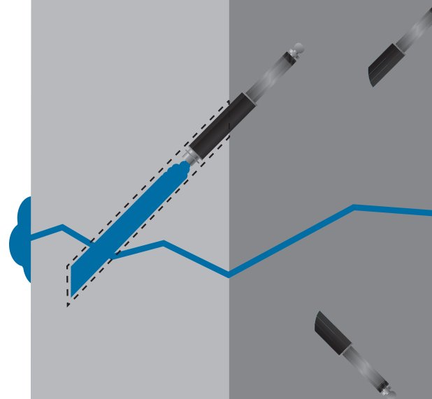
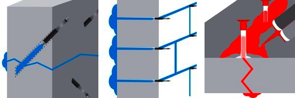
In the majority of cases, injection packers should be arranged in a staggered manner by alternating drill holes to the left and right of the crack while drilling at a 45-degree angle toward the crack, thereby forming a stitch grouting pattern. This method enhances the likelihood of intersecting the crack during drilling and reduces the probability of concrete cracking and spalling during packer installation or the high-pressure injection process. Injection should commence from the bottom and proceed upward.

45 Degree Angle Drilling and Packer Placement

The optimal method for packer placement involves positioning at a 45-degree angle. For structures with a thickness exceeding 6 inches (12-15 cm), SealBoss recommends a 45-degree angle as the most effective strategy for intersecting the crack at the midpoint of the structure. This is accomplished by initiating drilling a few inches to the left or right of the crack at an angled trajectory toward the crack itself, rather than drilling directly into it. This technique enables the requisite “inside-out” product flow for optimal crack penetration.

For instance, in a 10-inch thick concrete wall, one should move approximately 4-5 inches (8-10 cm) away from the crack and drill at a 45-degree angle toward it to attain the desired target. Initiating drilling with a straight entry and subsequently angling the drill at the required angle is beneficial.

Typical drill spacing along the crack’s surface ranges between 6-12 inches (10-20 cm) depending on the crack’s thickness. Hairline cracks necessitate closer spacing than larger cracks, as the material will not travel as far. Stagger drill holes from one side of the crack to the other, intersecting the crack during drilling.

Optimizing Drill Hole Distance from the Crack 

When determining the spacing of drill holes from a crack for chemical grout injection, it is essential to understand the relationship between the hole’s distance from the crack and the depth at which it intersects the crack. Here is a detailed explanation:

  • Depth of Intersection: The greater the distance between the drill hole and the crack, the deeper is its intersection with the crack inside the structure, leading to a deeper point of injection.

  • Considerations for Thicker Structures:  In thicker structures, a deeper injection point is usually favored. Yet, it is essential to factor in the drill bit’s length and reach, as they play a crucial role in determining the optimal distance for the drill hole. Always allow for a margin of error and ad at least a margin of 2 inches to the calculated drill bit reach needed. 

  • Avoiding Dead-End Drill Holes: A drill hole that misses the crack cannot facilitate the injection of the chemical grout into the structure. Such holes are termed “dead-end drill holes” and are ineffective for the purpose of grout injection.

Determining the Required Minimum Length for a Drill Bit

When drilling at a 45-degree angle, we encounter a specific triangle called the 45-45-90 triangle, which follows the principles of the Pythagorean theorem.

In this 45-45-90 triangle, both legs, marked “X”  are of equal length. X is the distance the drill hole is placed away from the crack. Therefore, when drilling at a 45-degree angle, if we assume the crack is perpendicular to the surface, the depth at which the drill hole intersects the crack will be the same as the distance of the drill hole from the crack. To determine the minimum drill depth, or the distance from the drill hole surface to the crack, use the formula:
Distance from crack X √2, which is approximately 1.414.

To simplify and account for variations we use the factor 1.5 to calculate the absolute minimum drill hole depth necessary to intersect the crack. 

For a 5-inch distance from the crack, the calculation would be: 5 × 1.5 = 7.5 inches. Therefore, the drill hole should be at least 7.5 inches deep to guarantee intersection with the crack for injection in near perfect conditions.

For a 6-inch distance from the crack, the calculation would be: 6 × 1.5 = 9 inches. Therefore, the drill hole should be at least 7.5 inches deep to guarantee intersection with the crack for injection in near perfect conditions.

Now add at least 2 inches of drill bit reach to the calculation. It is essential to remember that not all cracks might run perfectly perpendicular to the surface, so always consider the specific conditions of your project.  

In summary, while determining the placing of drill holes, it is important to balance the desired depth of injection with the capabilities and reach of your drilling equipment to ensure effective grout injection.Remember, the effective reach of a drill bit and its actual length differ.

Always ensure your drill bit has the necessary length to effectively intersect the crack!

General Injection Packer Preparation – Drill and Flush


Safety Gear

Consistently wear appropriate protective gear and goggles, adhering to data sheet and SDS instructions.

Cleaning

If required, clean the crack or joint’s face using a wire brush, pressure washing, or similar method. A clean surface facilitates the identification of cracks and problematic areas.

Spacing

Mechanical injection packer spacing, also known as port spacing, is contingent upon various site conditions such as crack depth and width, substrate thickness and state, water flow rate, and the product’s physical and chemical properties.

An 8-inch (20 cm) to 1-foot (30 cm) on-center spacing is suggested for the majority of situations. Hairline cracks necessitate tighter spacing compared to wider cracks. The tighter the cracks, the closer the required spacing, as the product must travel deeply enough into the structure to form a permanent seal.

Determine the spacing, pattern, and depths of the drill holes. Based on the crack’s width, space the packers at a distance of approximately 6-18 inches (10-45 cm). The tighter the cracks, the closer the required spacing. Hairline cracks result in limited water stop and leak-seal grout travel, necessitating tighter packer spacing, while wider cracks permit easier flow and broader packer spacing.

Stagger drill holes from one side of the crack to the other (left/right), thus forming a stitch grouting pattern. This technique increases the chances of intersecting the crack during drilling while decreasing the likelihood of cracking and spalling the concrete during packer installation and the high-pressure injection process.

Typically, injection should begin at the bottom and move upward, pushing the product against gravity and water flow, thereby achieving a higher density in the process.

Exceptions to the 45 Degree Injection Rule – Straight Drilling

As with any rule, the catchy SealBoss 1-2-3 at 45-Degree Rule has its limitations and exceptions. Here are three notable examples:

  • Drilling into Joints
    Drilling into joints, such as concrete tunnel segments, is predominantly performed in a straight manner.

  • Thinner Stuctures
    Concrete structures with a thickness of less than 6 inches may not permit angle drilling, as this can result in cracking and spalling of the concrete.

  • Badly Deteriorated Substrate
    Similar issues can occur in severely deteriorated concrete substrates and in concrete of inferior quality. In such situations, it is recommended to drill and install packers directly into the crack without completely penetrating the structure.

SealBoss offers an extensive range of injection equipment and pumps to accommodate your project. Consult a SealBoss technician for detailed information and assistance. We look forward to helping you with your project.

Drill Dust

When drilling deeper holes, periodically extract your drill bit to remove drilling dust and prevent your drill from binding up.

Rebar

Most concrete structures contain rebar steel reinforcement to provide structural strength. In an ideal, crack-free structure, concrete protects the rebar from corrosion by insulating it from moisture and air while maintaining a high pH environment. However, when cracks form, this shield is compromised, allowing air, environmental gases, and water to cause carbonation, and subsequently corrosion of the rebar, which  forms rust expands to expands its original volume. The expansion of rusted rebar exerts high forces against the concrete, resulting in further deterioration, cracking, and spalling. Chemical grout injection protects rebar and can mitigate these processes.

Rebar often slows down the drilling process. When your drill bit contacts rebar, the sound changes, the quantity of drilling dust may be reduced, and the progression slows down or may even stop.

Some drill bits enable drilling through rebar, although this is generally not recommended and may even be prohibited, as it can weaken the concrete structure. In such cases, relocating the drill hole is the only option. If you repeatedly hit rebar, consider drilling straight into the crack. Dead-end drill holes, the holes that are not used for injection, must be patched and sealed before injection to prevent leakage.

Flushing / Cleaning Drill Holes Prior to Injection

Overview

Drilling debris can thicken the product during injection, resulting in higher injection pressures and reduced penetration in fine cracks. It is best practice to remove concrete dust and debris from the drill holes by flushing with a water hose until clean water is observed. You can use a water hose to flush debris from the hole.

Vacuuming out the dust can also be helpful if flushing is not possible.

Blowing out the debris is another option; however, be aware that dust can be an inhalation hazard, and appropriate gear is mandatory.

Flushing / Cleaning of holes is not necessary if water is actively running from your drill holes.

Drill Hole Water Flushing Detail

Low Pressure Flush

For low-pressure flushing, simple tools like a plastic water squeeze or spray bottle suffice. This method can remove debris from the drill hole and introduce water into the drill hole.

If available on site, a water hose can be used to flush the drill holes.

Using a Dedicated Flushing Water Pump

A dedicated water injection pump is suitable for both low-pressure drill hole flushing with a hose and on-site pressure crack flushing with water through injection packers.

While drill hole flushing serves to remove debris from the hole only, high-pressure water flushing can provide insights into material flow, expected product penetration distance, and introduce moisture to enhance product reactivity.

For such high-pressure applications, a dedicated water flushing pump is essential.

After clearing the drill hole, an injection packer is positioned. The water pump is then linked to channel water under high pressure via the injection packer into the into the crack, flushing it in the process.

If the crack remains unresponsive to taking on water, it might indicate that the hole is not linked to the crack. In such cases, a new drill hole has to be established and retested with water.

While high-pressure flushing is not typically required for most injection projects, it can offer benefits in specific scenarios.

It is imperative not to use the same pump for water injection that you use for dispensing polyurethane resin. Given that polyurethanes are activated by water, even the slightest moisture can result in pump malfunction.

Final Thoughts

Equipment limitations may render flushing infeasible; however, most injections will succeed without additional water introduction, even in seemingly dry crack environments. If the product does not immediately contact water, it will cure over time as natural moisture in the concrete stimulates curing and hardening, potentially at a slower pace.

Additional Injection Packer Installation Recommendations

Mechanical Packer Fundamentals

For optimal performance, packers and drill holes must possess adequate quality to endure injection pressures without leakage or displacement within the crack. Notably, even superior packers may rupture or leak under certain conditions. SealBoss Mechanical Packers, available in various sizes and designs, are recommended for pressure injection. These packers feature a threaded shaft with a rubber base; upon insertion, tightening the shaft compresses the rubber within the drill hole, generating a compression seal. Standard packer diameters range from 1/4 to 3/4 inches, with industry norms between 3/8 and 5/8 inches. In poured concrete substrates, drill holes serve as solid channels directing resin to the crack, enabling the use of shorter packers. In substrates with potential voids, such as block walls, stone, and brick, SealBoss advises employing longer packers to ensure a definite grout delivery channel to the crack being sealed.

Mechanical Packers Installation

To seal against the drill hole, mechanical packers require tightening, which expands the rubber seal. Packers may be pre-tightened by hand to seat the rubber snugly, approximately 1/4 inch (5 mm) inside the drill hole. Correct installation prevents concrete cracking around the drill hole’s exterior. Depending on packer design, using an appropriate ratchet/nut, wrench, or electric driver for tightening is highly recommended. Packers should be securely tightened to withstand injection pressures without over-tightening.

SealBoss Hammer-In Ports

SealBoss Hammer-In Ports are also frequently utilized. These ports are seated using a hammer at moderate force, with an electric driver or hand tool and a suitable socket employed to screw the zerk fitting into the port. Hammer-in ports typically do not achieve the same injection pressures as mechanical packers and should be reserved for applications where maximum injection pressures are not essential.

Packer Connectors

Packers are typically equipped with a quick-connect system, either a zerk type or button head/slide coupler type.

Zerk Type Connector

The zerk type is most prevalent. Applicators must push the coupler over the zerk fitting and maintain alignment with the packer. To disconnect, applicators “break” the connection by pushing the connector sideways.

Button Head / Slide Coupler

The button head type provides a more secure connection. The operator slides the coupler on and off the packer, ensuring a secure, tight connection that is less prone to unintended disconnection and leakage. When executed properly, the applicator does not need to hold the coupler in place, a significant advantage in overhead injection and instances requiring large product volumes through one packer.

SealBoss Packers

SealBoss offers an industry-leading array of injection packers and ports for diverse situations and requirements. Contact a SealBoss representative for packer recommendations tailored to your project.

Injection Products


Before You Start Injection

Before injection, review the product datasheet instructions. Ensure your pump is in fully operational condition and completely devoid of moisture before preparing SealBoss Water Stop and Leak Sealing Products for injection.

It is prudent to flush the pump with SealBoss R70 before using any resin/foam grout.

Injection Procedure

When products are prepared for injection, have a cup available to dispose of some resin to ensure purity. Start the pump at the lowest pressure setting. After connecting your grout injection hose to the secured and tightened packers, initiate the injection process.

Use the shut-off valve at the injection hose’s end whenever the hose is moved, remember that some pumps need to be manually stopped .

Starting from the bottom, securely connect your injection line to the packer and commence with the lowest pressure capable of moving resin into the crack. Generally, injection pressure will decrease as material flows, but pressure may need to be increased as products thicken and move into tighter cracks and fissures.

Maintain a slow injection rate as resin begins to show and flow from the crack. Pausing and restarting the process for a minute may be necessary to allow material reaction and thickening.

Monitor consumption rates and cease injection when consumption equals leakage. A typical observation involves reduced water flow from the crack’s face and/or reacting material exiting the crack’s face. This indicates successful penetration and results.

If the product does not advance along the crack, disconnect and proceed to the next port. Applicators must ensure sufficient material is injected into each crack to achieve optimal product density for a durable seal.

It is recommended to inject three to five packers while observing product flow, travel, and refusal from the crack.

Reinjecting those three to five packers—typically up to three times (1-2-3 at 45 degrees) or until product refusal—is crucial. The crack must be adequately filled with as much product as possible without excessive product loss from the crack. Sufficient material consumption and product density in the injected area must be monitored to achieve a solid and successful repair.

Injection Packers that continue to consume considerable product amounts should be injected a third time or as often as necessary to create a permanent seal.

SealBoss Oakum Soakum Technique

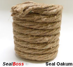
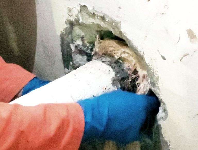
In cases where excessive resin flows out or washes out due to high water flow, resin-soaked SealBoss Oakum can be employed to form a temporary plug, allowing the product time to react, expand, and seal.

Caution: Be prepared for the possibility of product ejection from the structure or around drill holes, as well as packer blowouts. High-pressure injection equipment may cause product to travel further than anticipated, potentially appearing several feet from the injection point. Small cracks may become visible after the injection process.

Quality Injection Job

Injection often necessitates a two-person team, with one individual operating the valve and hose while another manages the pump. Create a dense seal! Inadequate material consumption alone can yield differing results in the same injection application. If the crack is not accepting any product, it may be due to insufficient drilling depth or crack direction on the opposite side. In such cases, drill from the opposite side of the crack and ensure intersection with the crack.

Packer Removal

Once the material has fully cured, packers can be removed by loosening the shaft. Some applicators opt to leave the rubber base in the wall and patch the drill hole, while others remove the entire packer before patching. In certain injection applications, packers may remain in place permanently. This decision is at the discretion of the applicator or owner. A final cleaning of the crack’s face is necessary to remove cured product using a wire brush, pressure washing, or other appropriate methods. The substrate is then prepared for the final finish.

SealBoss R70 Pump Flush for Clean-up

DO NOT CLEAN WITH WATER. If allowed on the job, initially flush all dispensing equipment with a small amount of solvent, such as xylene, to cut the product. Follow this step by generously flushing with SealBoss R70 Pump Flush & Cleaner to protect hoses and lubricate the pump. Avoid using solvents for the final flush, as this can reduce the lifespan of your equipment.

Exception – Equipment for SealBoss 2400 Acrylate is cleaned with water. Consult the data sheet for details.

Inquiries, Comments, or Requests?

Contact us now at 714-662-4445 and request your technical consultant!

Contact Your SealBoss ® Technician

Water Stop Injection Pro Kits

Water Stop Injection Pro Kits

Water Stop Injection Pro Kits

Engineer Focused Leak Sealing Injection Training

Elevating Structural Integrity with Water Stop Injection Pro Kits: A Paramount Educational Initiative

The Paramount Group recently hosted an enriching educational event tailored for UG2 Engineers across its six San Francisco properties, featuring a dynamic “lunch and learn” session coupled with an engaging hands-on demonstration led by SealBoss Corp. Concrete Solutions. This event marks a significant stride in addressing the escalating challenge of groundwater intrusion, a problem intensified by the recent unprecedented downpours across Northern California. The widespread impact has led to a notable shortage of specialized contractors, escalating the urgency for effective solutions.

As a consequence of the recent record-shattering downpours, groundwater intrusion has grown into a pervasive issue affecting a multitude of properties across Northern California. This concurrent impact on the region has given rise to a scarcity of specialized contractors equipped to handle such challenges, further complicating the situation for affected parties.

Training Spotlight: Empowering Contractors and Engineers with Water Stop Injection Pro Kits

In response to this urgent need, Paramount Group has taken a strategic step by empowering their on-site engineering teams with advanced Water Stop Crack Injection Pro Kits. 

The initiative includes comprehensive training sessions aimed at enhancing the teams’ proficiency, ensuring the secure and adept use of these state-of-the-art tools. This forward-thinking approach not only enhances the engineers’ capabilities but also ensures rapid, in-house resolution of groundwater intrusion challenges, upholding the highest standards of property maintenance.

By supplying Water Stop Crack Injection Pro Kits and organizing comprehensive training sessions, the company guarantees the secure and efficient application of waterproofing and leak sealing injection grout systems.

This initiative is projected to yield substantial cost savings, potentially amounting to thousands of dollars annually per property. It underscores Paramount Group’s dedication to innovative problem-solving and the continuous professional growth of their engineering personnel.

We take great pride in offering comprehensive educational programs targeted at engineers, distributors, and contractors worldwide, focusing on the practical application of our products and technology. These sessions are designed to foster a deeper understanding of effective leak sealing techniques and the strategic use of Water Stop Injection Pro Kits.

For more details about our comprehensive classroom services, hands-on training, and informative “lunch and learn” sessions, please reach out to our expert technical sales team at 714-662-4445. Engage with us to elevate your engineering solutions and safeguard your properties against the challenges of water intrusion.

SealBoss Engineer Training
SealBoss Training Engineer Testimonial

It brings us great pride to provide all-inclusive educational programs for engineers, distributors, and contractors around the globe, focusing on the effective utilization of our products and equipment.

For additional information regarding our classroom services, on-the-job training, and lunch and learn sessions, please don’t hesitate to reach out to our knowledgeable technical sales staff at 714-662-4445.

Contact Your SealBoss ® Technician

Hydrophilic Waterstops

Hydrophilic Waterstops

Hydrophilic Swelling Waterstop

SealBoss Swell Tape and Swell Caulk

Introduction to Hydrophilic Waterstops

Hydrophilic waterstops have emerged as an essential component in modern concrete construction, particularly in ensuring the watertight integrity of various below grade structures such as parking garages, subterranean warehouses, stores and tunnels.

SealBoss, a leader in the field of specialized below grade waterproofing, offers an array of hydrophilic waterstops that are renowned for their high quality and cost-effectiveness.

These products are specifically designed to meet the demanding water containment requirements of today’s construction projects.

The Functionality Behind Hydrophilic Waterstops

The term “hydrophilic” refers to the affinity for water, and in the context of waterstops, it signifies the material’s ability to swell upon contact with water. This swelling action is crucial as it forms a hydro-active compression seal that effectively blocks water infiltration.

Unlike traditional waterstops, the hydrophilic variants offered by SealBoss do not rely solely on adhesion to the substrate, but adapt to leakage by expansion, making them suitable for joints involving diverse materials.

SealBoss Swell Tape – Swelling Joint Sealer Strip: A Versatile and Effective Solution

One of the flagship products in SealBoss’s hydrophilic waterstop range is the SealBoss Swell Tape. This strip-applied, preformed hydrophilic polymer waterstop tape is specifically engineered for the waterproofing of concrete joints. The unique formulation encapsulates hydrophilic polymers into a rubber base, creating a highly effective, durable, and moisture-activated swellable compression seal. When exposed to moisture or water, the material swells, thereby generating a compression seal that ensures water tightness.

Applications of SealBoss Swell Tape

The versatility of SealBoss Swell Tape makes it an ideal solution for a broad spectrum of applications. These include:

  • Sealing construction joints in buildings and infrastructures
  • Waterproofing pipe penetrations to prevent leakage around pipes
  • Ensuring watertight integrity in manhole joints
  • Application in precast concrete segments for structures like bridges and tunnels
  • Addressing cold joints, where new concrete meets old concrete
  • Use in tunnel segment joints for subterranean constructions
  • Waterproofing poured wall joints in both residential and commercial buildings

SealBoss SwellCaulk: Complementary Hydrophilic Waterstop Caulk

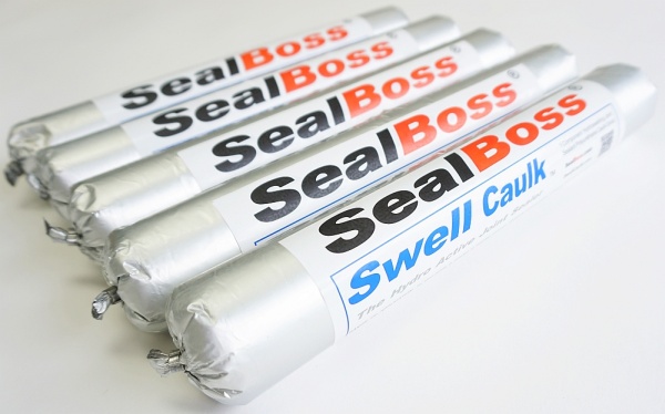
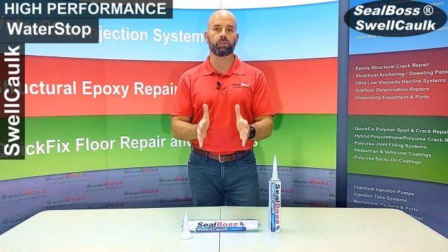
In addition to the Swell Tape, SealBoss offers the SealBoss Swell Caulk  – a hydrophilic waterstop caulk designed to complement the Swell Tape system.

SwellCaulk serves as both a waterstop and an adhesive, enhancing the effectiveness of the Swell Tape in concrete joint applications. It is especially recommended for complex joint configurations where additional sealing and adhesion are necessary.

Conclusion: The SealBoss Hydrophilic Waterstops Advantage

The SealBoss range of hydrophilic waterstops, including the Swell Tape and Swell Caulk, represents a significant advancement in water containment technology.

Their effectiveness, versatility, and ease of application make them an excellent choice for a wide range of construction projects.

By choosing SealBoss products, construction professionals can ensure the long-term integrity and durability of their structures against water infiltration.

Click here for more information on SealBoss  Swell Tape & Swell Caulk Products

Contact Your SealBoss ® Technician

Injection Packers

Injection Packers for High Pressure Crack Injection Applications Overview

  • Injection Packer Materials – Injection Packers bodies are constructed from various materials including steel, brass, aluminum, zinc, or plastic.

  • Dimensions – Injection Packers are available in many sizes, lenghts and diameters to meet the application demands, injection products, injection pressures, and injection volume and flow requirements.

  • Mechanical Packers – Injection Packers, specifically the mechanical injection packer types, short “Mechanical Packers”, are fitted with a compression rubber sleeve mechanism,  to lock securely into the packer placement drilled hole.

  • High Injection Pressures – Mechanical Injection Packers, are designed to work in high pressure injection conditions from several hundred psi up to several thousand psi. (100 – 10,000 psi or 6 – 600 bar).

  • Injection Packer Application Procedures – Injection Packers are often placed in a staggered pattern along the crack in a  45 degree angle. This is known as the standard SealBoss  1 – 2 – 3 – 45  Degree Method. Other methods and packer placement  techniques also apply depending on the requirements of the application.

Injection Packers are designed to safely and securely connect your Injection Equipment to the concrete substrate, in order to deliver the injection chemical resin – often under high injection pressures – to the area of repair.

Injection packers must be of suitable construction and sturdiness, as they have to withstand low and high injection pressures as needed, and allow for adequate flow of product. Their design must permit easy installation and removal, as needed – while being cost- effective.

Injection Packers Details Explained

Information About Injection Packers
Packer Materials & Types

Injection packers and ports are essential tools for successful grout and epoxy injection in construction and repair projects. These tools are generally categorized into two types: insertable mechanical injection packers and surface-mounted ports.

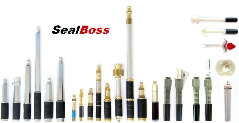
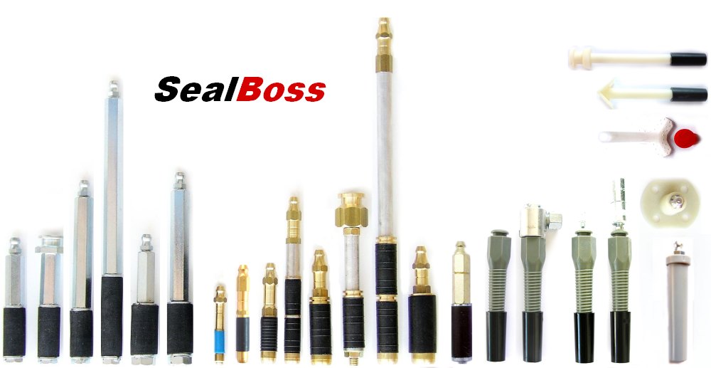
SealBoss offers a wide selection of injection packers made from steel, brass, aluminum, zinc, various metal alloys, and plastic.’

Each material and design caters to specific substrates, applications, and contractor preferences, ensuring a tailored solution for any injection scenario.

Mechanical Injection Packer Features
Premium mechanical packers incorporate a rubber sleeve with a threaded shaft. When tightened, the sleeve compresses to form a seal within the drilled hole. A soft, expandable rubber ensures optimal grip and supports high injection pressures.

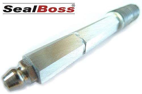
SealBoss Steel Injection Packers are most robust, high-performance packers designed for high-pressure resin injection in demanding applications. 
Known for their strength and durability, SealBoss steel packers are suited for high-pressure injections, icnluding polyurethane, epoxy, and acrylate/acrylic gels. Available in multiple designs, most include a rubber sleeve and a larger top washer for secure installation.

These packers are an efficient, industry standard setting, and effective solution for structural repair and waterproofing, trusted by professionals worldwide.

  • Steel Construction Injection Packers: Set the standard – built to withstand high injection pressures and provide a durable, reliable seal.
  • Interchangeable Fittings: Come with button head and standard and low pressure zerk fitting options, enhancing versatility for various injection systems.
  • Anti-Return Valve: Located in the fitting, it prevents resin backflow, maintaining the integrity of the injection.
  • Port-to-Port Resin Travel:  Removeable valve allows for observation of resin movement, ensuring controlled application.
  • Wide Size Range: Suitable for various applications, from small repairs to large-scale projects.
  • Compatibility: Works with all injection resins, including low-pressure applications.

Steel Injection Packer Button Head 16-60S SealBoss


Brass, Aluminum, and Zinc Packers
These materials offer economical alternatives to steel with similar functionality. Although they have lower strength, some designs allow the shaft to be broken off after injection, leaving a flush surface—a benefit for certain projects.

SealBoss Aluminum Injection Packers are economical, lightweight options for standard resin injection tasks. 

Modeled after the SealBoss S-Type steel, these aluminum packers offer a very budget-friendly solution for typical crack injection scenarios, ideal for professionals looking to reduce costs on routine jobs.

  • Aluminum Construction: Provides a secure fit and is lighter and more affordable to ship than steel alternatives.
  • Cost-Effective: The most economical option for crack injection, saving costs on large projects.
  • Anti-Return Valve: Located in the zerk fitting, preventing resin backflow during application.
  • Standard Application Use: Suitable for everyday injection needs and non-critical applications.

Aluminum Injection Packer - Aluminium Injection Packer - SealBoss Evolution


SealBoss Brass Injection Packers are durable and versatile packers designed for resin injection. 

These economical alternatives to steel packers are widely used in construction for their built in zerk fittings, reliability and cost-effectiveness.

  • Available in a Wide Variety of Sizes, Thicknesses, and Lengths: Options range from compact to extended-length injection packers, designed to meet the most demanding jobsite requirements.
  • Monolithic Zerk Fitting:No separate zerk fitting ensures smooth installation procedure and secure attachment.
  • Anti-Return Valve in the Packer Base: Prevents resin backflow, even if the neck is unscrewed or broken off.
  • Defined Breaking Point: Allows clean removal after use.

13-100B-BRASS-PACKER-SEALBOSS

SealBoss Standard Zinc Packers are strong, affordable, and reliable packers designed for standard grout injection. 
Zinc injection packers are another choice for general injection applications, offering quick installation and efficiency in everyday crack repair and sealing tasks.

  • Bottom Anti-Return Valve: Enables head removal after grout injection, preventing backflow.
  • Packer Neck Hexagon: Easy tightening packer neck
  • Common Industry Size: Provides adequate surface seal area for a secure grip at an economical price.

13-70ZI-Zinc-PACKER-SEALBOSS

SealBoss Plastic Buttonhead Injection Packers and Hammer-In Ports  for large Volume Injection nad Fast Installation. 

 These plastic packers offer versatile options for resin grout injections, covering applications that metal-style injection packers may not accommodate. 

The SealBoss Hammer-In or Bang-In packers require only a hammer to secure in place. These packers create a compression seal without a sleeve, making them ideal for quick installation. However, they are best suited for low-pressure injections due to a lower friction fit.

  • Buttonhead Packers: Feature a large anti-return valve and inner diameter for high-volume material flow, ideal for low-pressure applications like curtain injection and slab lifting.
    Hammer-In Ports: Quickly installed without the need for tightening, providing a fast, economical alternative to mechanical packers in certain applications.
  • Wide Compatibility: Suitable for use with epoxy, grout, and various SealBoss injection systems, including manual, pneumatic, and cartridge injections.

5-8 PLASTIC BUTTON HEAD-ZERK-PLASTIC PACKER-SEALBOSS

Injection Packer Fitting Types 

Packers often feature either a zerk or button head fitting for connection:

  • Zerk Fitting: Commonly used for medium to high-pressure applications, offering quick connection and disconnection.
  • Button Head Fitting: Suitable for high-volume applications, providing a superior connection with reduced leakage, especially beneficial for single-operator use.

Surface Ports

Surface-mounted epoxy injection ports are suitable for lower-pressure applications or when drilling isn’t feasible. They can be glued directly to the surface or placed within a drilled hole. Many have open designs for quick-release connectors and are equipped with caps to prevent backflow. Ports with zerk fittings are available for higher pressure needs, including specialized corner ports for 90-degree angles.

Injection Packer Dimensions and Specifications

Diameter
 A packer’s diameter affects injection pressure capacity and fit within drilled holes. Common sizes include 5/8” (16mm), 1/2” (13mm), 3/8” (10mm), and 1/4” (6mm). Larger diameters are generally more resistant to blow-outs and provide a stronger grip, especially for high-pressure and rock applications.

Length
Longer packers, ranging from 4″ to 6″, are ideal for deteriorated concrete or deep injections. They enable secure embedding within the substrate, minimizing the risk of spalling and bridging gaps in the structure.

Valve Placement

  • Top-Mounted Valves: Zerk and button-head valves allow for observing grout travel during injection. Button-head valves offer a stronger connection with less leakage.
  • Bottom-Mounted Valves: Positioned on the stem, these valves allow the packer’s head to be removed after injection, keeping the seal intact and facilitating patching.

Conclusion
The 1/2″ (13mm) diameter mechanical injection packer is often a reliable starting point for most projects. Steel packers are ideal for very high injection pressures, though economical considerations may favor alternatives like aluminum, brass, or zinc for a variation of scenarios including jobsite conditions and budget.

Larger diameter injection packer can reduce blow-out risks, while longer packers are recommended for angled drilling and degraded substrates.

High-flow applications at lower pressures may benefit from the 5/8″ button-head packers, while the 3/8″ Hammer-In packers could be suited to low-pressure work in high-quality concrete.

SealBoss offers a diverse range of packers and ports, including surface ports with zerk fittings for smaller epoxy and polyurethane jobs and injection screws for cold joint applications. Ensuring a secure fit and selecting the appropriate packer type is crucial for technician safety and successful injection results.

Injection Packers for Crack, Water Stop and Leak Sealing Injections

SealBoss injection packers connect the injection equipment (applicator and injection pump) with the structural substrate to serve as the port of entry – or filler neck – for a large variety of injection resins and chemical grouts into concrete mediums.

Our Packers are made from a various metals including steel, brass, zinc, aluminum / aluminium or plastic.  Packers are typically equipped with either a zerk fitting or button head fitting for easy and secure connection to the applicator. The button head type offers the most secure connection in overhead, high pressure and high volume appplications.

Conditions of the jobsite, environment and material determine the type, material, and build of packer, in order to achieve the best injection results. SealBoss provides a very large selection of injection packers to meet all professional needs.

Injection Packers – Installation Types

Based on injection requirements and injection products to be used, we distinguish between borehole packers and surface mount packers, also known as surface ports.

Cylinder shaped, borehole type injection packers are typically used for high pressure injection with polyurethane bases, water stop and leak-seal resins and injection foams.

Borehole style packers work very well in wet and otherwise demanding environments, such as deteriorating concrete substrates.

We further differentiate between mechanical packers with a tighten-down and screw-in mechanism, and hammer-in technique packers.

The seal of the aforementioned packers is achieved by friction between the packer body in the drill hole and the surrounding substrate.

Surface mounted ports are mostly used for structural epoxy injection where a non-destructive injection process – no drill holes allowed procedure – is specified. 

Surface mounted packers or surface ports are glued to the surface of the substrate and rely on the bond strength of the adhesive, such as SealBoss 4500 epoxy paste adhesive. Surface port placement is best performed on a dry substrate and can be difficult in wet environments with active water leaks. 

Preparatory work

Step1 – Structure / Substrate / Product Analysis

  • Condition of structure, environment and climate
  • Chemical rout / resin specified
  • Injection pressures expected  (high pressure vs low pressure)

Step 2 – Packer Choice

  • Select suitable injection packers.
    Please consult with your SealBoss Technical Rep.

Installation

Installation procedures depend on the conditions found at the jobsite. SealBoss provides detailed information online and in printed publications. Please contact your technical rep.

The size of the drill holes equals the stated diameter of the mechanical packers and hammer-in packers; the borehole depth varies according to the conditions and requirements.

Drill holes are typically made at an angle of approx.  45° depending on the wall thickness and other conditions.  All drill dust and debris must be removed from the boreholes.

Final work

  • Remove or knock-off the mechanical packers / hammer-in ports / surface packers as specified
  • Patch the drill holes with suitable mortar

Related Links

Contact Your SealBoss ® Technician

Highway Spall, Crack, and Pothole Repair

Highway Spall, Crack, and Pothole Repair

Highway and Road Repair Polymers

Introduction

In the comprehensive field of highway and road maintenance, addressing the challenges of spalls, cracks, potholes, and birdbaths in a quick and timely fashion is crucial for ensuring the public safety and longevity of road infrastructure. Advanced polymer products have significantly enhanced traditional repair methods, providing solutions that are not only convenient, rapid and extremely durable but also environmentally friendly.

Who hasn’t felt the frustration of constantly scanning the road for large cracks and gouges, only to still end up jolting through an unexpected major pothole?

This article provides an overview into the intricacies of highway damage, the pivotal role of polymer products in contemporary repair techniques, and provides a quick guide on the application of high strength and fast curing polyurethane repair systems by the example of  SealBoss ® Highway and Road repair QuickFix polymer. We show how this innovative product line can be effectively utilized to combat common roadway damages, thus contributing significantly to maintaining safe and efficient transportation networks.
Play Video about SEALBOS-6060-POLYUREA-ROAD-REPAIR

Quick Road Repair Solution

Highway Spall, Crack, and Pothole Repair: Advanced Solutions not only for Highways

The maintenance and repair of highways are critical to ensuring the safety and efficiency of transportation systems.

The same is true however for any road in our communities and cities. 

Spalls, cracks, and potholes are common issues that can lead to significant structural damage and pose risks to drivers. SealBoss® 6060 QuickFix offers a solution how these repairs can be conducted quickly and with permanence. 

Understanding Road Damage

Road and highway damage typically manifests as spalls, cracks, or potholes.

These damages can be caused by a range of factors, including thermal expansion, freeze-thaw cycles, excessive load, and environmental degradation. Addressing these issues promptly is vital to prevent further deterioration and ensure road safety.

The Role of Polymer Products in Highway Repair

Polymer products, particularly polyurethane-based compounds like SealBoss  6060 QuickFix, have emerged as effective solutions for repairing highway damages. These products offer several advantages over traditional repair methods, such as asphalt patching or cementitious repairs.

Key Advantages

  • Extremely Rapid Setting Time: Enables quicker return to service, minimizing traffic disruptions.
  • Deep Penetration: Ensures comprehensive repair by filling even the smallest cracks and voids.
  • Flexibility and Strength: Accommodates some structural movements while providing durable repair.
  • Chemical Resistance: Withstands exposure to various chemicals, fuels, oils, and environmental factors.
  • Ease of Application: Simplifies the repair process, allowing for efficient use even in challenging conditions.

SealBoss 6060 QuickFix: A Closer Look

SealBoss 6060 QuickFix is a two-part  polyurethane product designed for the quick and effective repair of concrete and asphalt surfaces. Its low viscosity allows for deep penetration into fine cracks and pores, ensuring a strong bond, and semi-flexible, long-lasting repair.

 Properties

  • Fast Cure: Moderate traffic loads can resume within 15 minutes at 70°F (21°C).
  • Temperature Versatility: Effective in temperatures ranging from -20°F (-29°C) to 120°F (49°C).
  • Aggregate Compatibility: Can be used with various aggregates for different repair needs.
  • 100% Solids and VOC Free: Environmentally friendly with no harmful emissions.

Application Guidelines

To achieve the best results with SealBoss® 6060 QuickFix, a systematic approach to application is advised.

Surface Preparation

  • Cleaning: Remove all debris, oils, and loose materials. For deep cracks, saw-cutting and thorough dust removal are recommended.
  • Drying: Ensure the repair area is completely dry before application.
  • Roughening: Expose clean, rough concrete or asphalt surfaces for better adhesion.

Mixing and Application

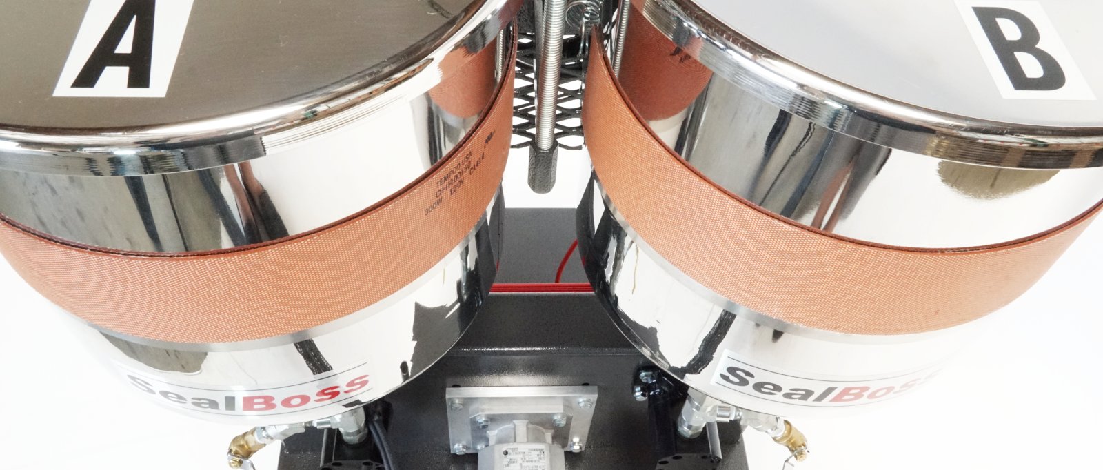
  • Mixing: Equally proportion components A and B is important. Use appropriate application equipment such as the SealBoss JM Pro2 Pump System.
  • Application Method: Apply the mixed product to the bottom of the crack or pothole, working upwards in layers. For deep repairs, alternate between applying the product and adding aggregate until the desired grade is achieved.
  • Curing: Allow the product to set, with traffic resumption times varying based on temperature conditions.
  • Equipment Care: Keep all equipment dry and clean to prevent contamination and ensure effective application.
  • Professional Use: The product is designed for professional use; consulting a SealBoss technician for specific project requirements is advisable.

Conclusion

The use of advanced polymer products like SealBoss® 6060 QuickFix represents a significant leap forward in fast and effective highway repair technology. These materials offer rapid, durable, and environmentally friendly solutions to common roadway damages. By understanding the properties and application techniques of these products, professionals can ensure effective repairs, ultimately contributing to safer and more reliable community roads and highways.

Related Links

Leak Sealing Methods

Leak Sealing Methods

Leak Sealing Methods

Leak Repair Overview

Leak Sealing Methods

Introduction

This article provides an overview of various methods for sealing leaks in concrete structures, emphasizing the importance of choosing the right technique based on factors like leak severity, material compatibility, and environmental considerations.

It highlights the most common methods: crack/joint injection and curtain grouting, which are essential for maintaining the structural integrity of concrete structures including tunnels, dams, commercial buildings, and foundations in general. The article also explores other leak sealing methods and options like epoxy resin injection and swellable waterstop caulking and water activated, expanding polymer strip tapes, discussing their applications and effectiveness.
Key considerations for method selection are outlined, including the size and location of the leak, material compatibility, effectiveness, environmental impact, cost-efficiency, regulatory compliance, and long-term sustainability.

The conclusion underscores the necessity of a comprehensive understanding of these factors for making informed decisions that ensure the safety and longevity of concrete structures.

Click icons for more information.

Ensuring Integrity in Concrete Structures

Water leaks in concrete structures can pose significant challenges, necessitating a thorough exploration of leak sealing methods. The integrity of structures like tunnels, dams, and foundations depends on the effectiveness of these methods. This article delves into the various techniques available, their applications, and the factors influencing their selection.

Crack/Joint Injection and Curtain Grouting

Crack/joint injection and curtain grouting stand out as the most prevalent techniques for addressing active water leaks in concrete structures. These leak sealing methods are the first line of defense against water intrusion, providing immediate solutions to maintain structural integrity.

Crack/Joint Injection – A Focused Approach to Leak Sealing

Crack/joint injection is a precise method that involves injecting polyurethane grout into specific cracks or joints where water is actively leaking. This technique is renowned for its effectiveness in sealing everything from minor seepage to significant leaks across various concrete structures, including walls, foundations, and commercial parking structures.

Curtain Grouting – Creating Barriers Against Water Intrusion

For larger leaks or when the precise leak location is elusive, curtain grouting is the method of choice. This leak sealing method involves injecting grout in a pattern that forms a waterproof barrier, particularly behind tunnel linings, offering a robust solution to water ingress.

Epoxy Resin Injection – Strengthening and Sealing Combined

While epoxy injection is primarily used for structural repairs, it also serves as an effective barrier against water intrusion. However, its use as a water stop is limited in areas with very active leaks.

Epoxy resins, synthetic polymers known for their strong adhesive properties, are particularly useful for sealing leaks in a variety of structures. Their ability to bond with concrete, some metals, and wood makes them a versatile option in the leak sealing methods arsenal.

Swellable Waterstops – Expanding the Fight Against Leaks

Swellable waterstops are hydrophilic materials that expand upon contact with water, effectively sealing off leaks. These are commonly implemented in construction joints and are highly effective in segmented concrete tunnels and structures.

Key Considerations for Leak Sealing Method Selection

The choice of a leak sealing method is influenced by several factors

  • Severity and Location of the Leak
    The size and accessibility of the leak are key in determining whether crack/joint injection or other methods like curtain grouting are appropriate

  • Material Compatibility
    The compatibility between the sealing material and the structure, such as concrete linings in tunnels, is crucial. Polyurethane grouts are compatible with concrete, while epoxy resins are better suited for metal surfaces

  • Effectiveness
    The method’s ability to seal the leak and prevent future occurrences is the foremost consideration

  • Environmental Considerations
    In environmentally sensitive areas, such as near water bodies, the selection of eco-friendly sealing materials is imperative

  • Cost-Efficiency
    Long-term costs, including maintenance and potential resealing, should be considered alongside the initial cost

  • Regulations – Compliance
    It is essential to select a method that adheres to local regulations to avoid any legal issues

  • Long-Term Sustainability
    The method should provide a durable solution to minimize the need for frequent repairs

Conclusion 

Leak sealing methods extend beyond crack/joint injection and curtain grouting. A comprehensive understanding of material compatibility, leak severity, and environmental impact is essential in selecting the appropriate method. By considering these factors and the outlined criteria, stakeholders can make informed decisions that offer long-term benefits, ensuring the safety and longevity of concrete structures.

Related Articles

Contact Your SealBoss ® Technician

Culvert Repair – Leak Sealing Injection

Introduction

Culverts are essential infrastructure components that facilitate water flow beneath roads and railways, preventing flooding and erosion. However, leaks and structural damage can compromise their functionality, posing environmental and infrastructural risks. Learn how innovative repair systems, employing injection techniques and grouting methods to seal leaks and stabilize surrounding soil, can be utilized to repair culverts economically and effectively.

This quick guide explores the significance of maintaining culvert integrity through advanced repair solutions, highlighting the importance of addressing leaks and cracks to ensure the longevity and reliability of these underground waterways.

What exactly is a Culvert?

Functioning like underground tunnels, culverts are subterranean waterways, enabling the movement of water from one side of a roadway or another type of traffic embankment to the other side.

From an aerial view, a culvert might be also likened to a bridge, purposefully crafted to enable the transit of vehicles or pedestrian traffic over a water passage.

Various materials can be employed to construct culverts, such as corrugated steel pipe, reinforced concrete, or other suitable materials.

SealBoss Culvert Repair Systems

SealBoss delivers comprehensive solutions for the rehabilitation and leak repair of culverts, effectively sealing water seepage through cracks and joints.

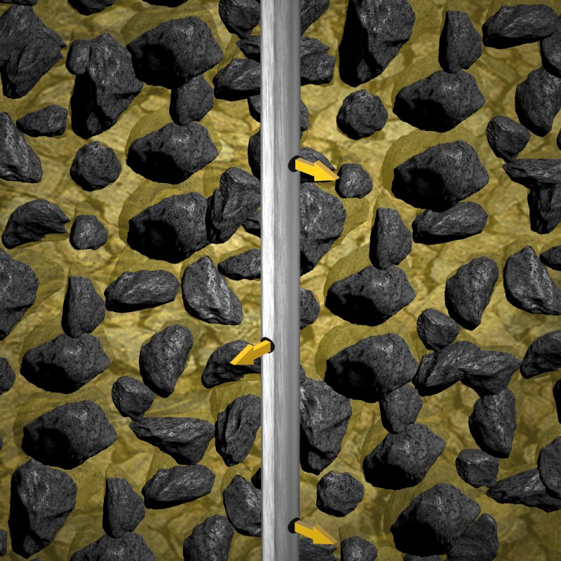
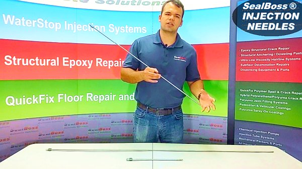
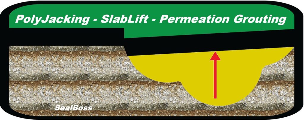
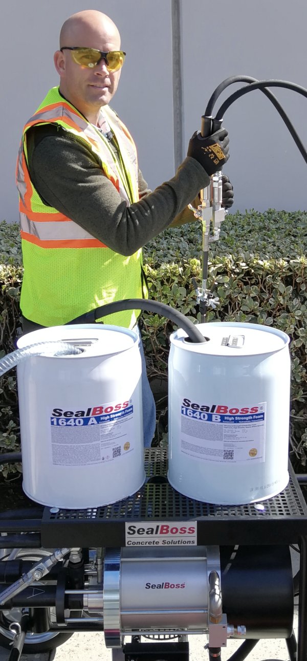
Moreover, the SealBoss Culvert Repair Injection Systems are designed to fill any existing voids in the soil that surrounds the culvert and to stabilize any loose soil that may impair the traffic embankment above it. This is accomplished using permeation grouting techniques, which make use of low viscosity polymer foam resin, grout injection lances and appropriate pumping equipment.

With our repair systems the service life of a culvert structure can be extended at reasonable cost.

Culvert Damages and Inspections

Culverts, also known as storm culverts, are tunnel-like structures designed to enable water to flow beneath obstructions such as roads, railways, or trails. Typically enveloped by soil, these culverts, when compromised by leaks, can contribute to soil erosion and the formation of sinkholes, thereby potentially damaging the overlying structures.

SealBoss presents a range of cost-effective solutions for repairing culvert leaks and stabilizing soil permeation. These systems are designed to effectively address water leakage through cracks and cold joints, as well as the accompanying issues of soil erosion.

Failure to address deteriorating and leaking culverts can result in significant, potentially dramatic damage and risk to both the environment and infrastructural elements.

Culvert Repair using Injection Grout – 
Applicable to Precast Pipe, Reinforced Concrete and other Material Culverts

SealBoss Injection Systems offer a versatile solution, suitable for culverts constructed from various materials.
Depending on the design and job site conditions, hydro-active grouts can be either directly injected into the concrete structure to seal cracks and voids, or introduced into the soil behind the structure. The latter method creates a waterproof curtain, fills voids, and permeates the soil to achieve stabilization and compaction.

Culvert Leak Repair from the Inside of the Structure

  • Crack & Joint Repair in Thick Concrete Culvert Structures – Drill into the structure in an angle
  • Curtain Injection / Soil Permeation – Drill through the structure to the outside of the culvert to fill the void and crate a curtain behind the structure
  • Set Injection Packers
  • For Soil Permeation Grouting use Injection Lances
  • Repair wide pipe penetrations with Seal-Oakum prior to injection
  • Start injection at the bottom if applicable
  • SealBoss Seal-Oakum /  Oakum Soakum Technique
    Always have SealBoss Seal-Oakum at the jobsite to plug larger voids and joints. The Oakum Soakum Technique explained here.

Culvert Leak Repair from the Outside  

  • If inaccessible, inspect culvert using survey camera equipment for leaks and damages
  • Map out and mark injection locations on the accessible structure above the culvert
  • Set Injection Lances to specification
  • Start injection to specification

SealBoss Culvert Repair System Training

We offer in-depth training on the application of high-pressure polyurethane water stop foam injection, using various SealBoss tools such as Injection Pumps, Hydro-Active Grout Systems, Injection Packers, Injection Lances, and Seal-Oakum.

A technical specialist from SealBoss will be present on-site to provide training and assistance to the contractor, with the ultimate aim of creating a work crew that feels confident and at ease with the application process.

The training will cover the use of pumps, setting up packers, and the injection procedure, including cleanup activities. Contractors will also be taught how to apply the catalyzed resin-soaked SealBoss Seal-Oakum.

Should you have any queries regarding culvert repair, feel free to reach out to our team of skilled SealBoss representatives. We can schedule an on-site consultation and provide comprehensive training on our injection systems.

Contact Your SealBoss ® Technician
Popular Posts
More Posts
Archives
Categories
Scroll to Top